
Image display device and light guiding device with diffraction elements

a technology which is applied in the field of image display device and light guiding device, can solve the problems of reduced resolution and reduced image resolution, and achieve the effect of less resolution reduction

Active Publication Date: 2020-02-18
SEIKO EPSON CORP
View PDF9 Cites 0 Cited by
  • Summary
  • Abstract
  • Description
  • Claims
  • Application Information

AI Technical Summary

Benefits of technology

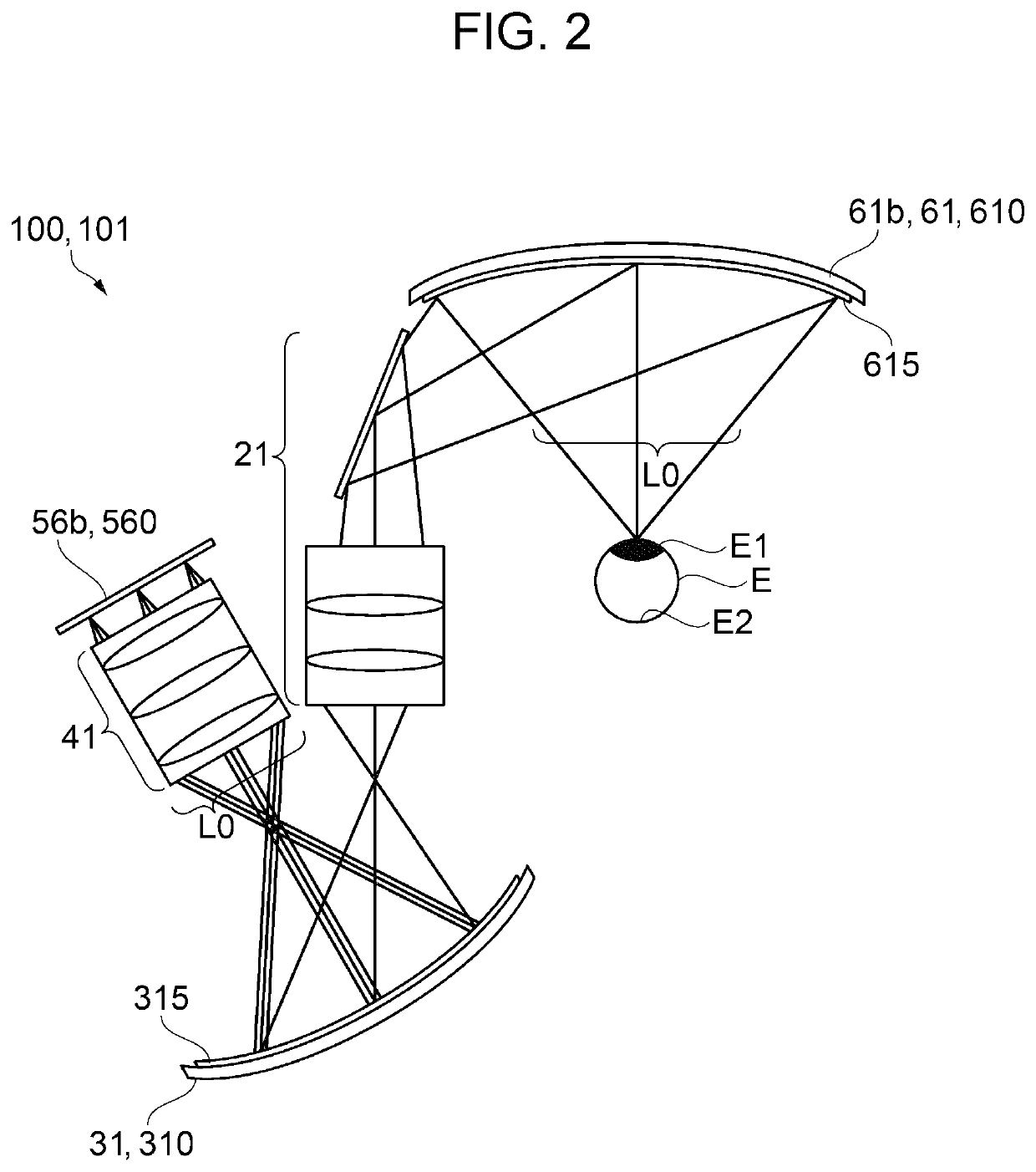
[0015]According to the application example, image light generated by the image light generation unit is directed to an observer's eye, through the projection system optical unit, the second diffraction element, the correction system optical unit, and the first diffraction element, enabling an image to be observed. Here, the image light is dispersed (deflected) by the second diffraction element into rays of light with wavelengths having different diffraction angles, the rays are focused substantially in parallel by the first diffraction element and emitted to the observer's eye. Therefore, a shift in diffraction angle due to difference in wavelength can be compensated for, and thus, an image without deterioration in resolution can be provided. Furthermore, since the image light is incident on the second diffraction element through the projection system optical unit, the second diffraction element can have a preferable configuration according to a position in the direction in a plane of the second diffraction element.
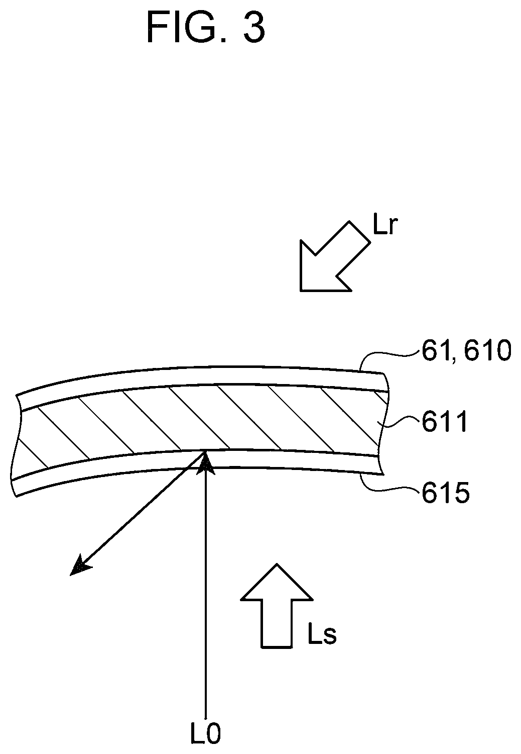
[0018]According to the present application example, the first incident surface and the second incident surface are formed into a shape in which a center portion has a recessed curved concave shape relative to a peripheral portion and have a function equivalent to that of a condenser lens. Therefore, a function of focusing the image light to an observer's eye is enhanced. Accordingly, high-quality image having a large angle of view can be effectively displayed.Application Example 3
[0022]According to the present application example, the plural kinds of interference fringes are provided corresponding to RGB colors of image light, and the image display device can effectively display a color image.Application Example 5
[0030]According to the application example, image light is directed to an observer's eye through the projection system optical unit, the second diffraction element, the correction system optical unit, and the first diffraction element, enabling an image to be observed. Here, the image light is dispersed (deflected) into rays of light with wavelengths having different diffraction angles by the second diffraction element, the rays are focused substantially in parallel by the first diffraction element, and emitted to the observer's eye. Therefore, a shift in the diffraction angles due to difference in wavelength can be compensated for, and thus, an image without deterioration in resolution can be provided. Furthermore, the correction system optical unit is disposed, and aberrations such as distortion can be reduced.

Problems solved by technology

However, when the image light has a spectrum width around a specific wavelength, a ray having a wavelength shifted from the specific wavelength causes reduction in image resolution.
As a result, the focal point on the retina E2 is shifted, resulting in reduced resolution.

Method used


Image

  • Image display device and light guiding device with diffraction elements
  • Image display device and light guiding device with diffraction elements
  • Image display device and light guiding device with diffraction elements

Examples


embodiment 1

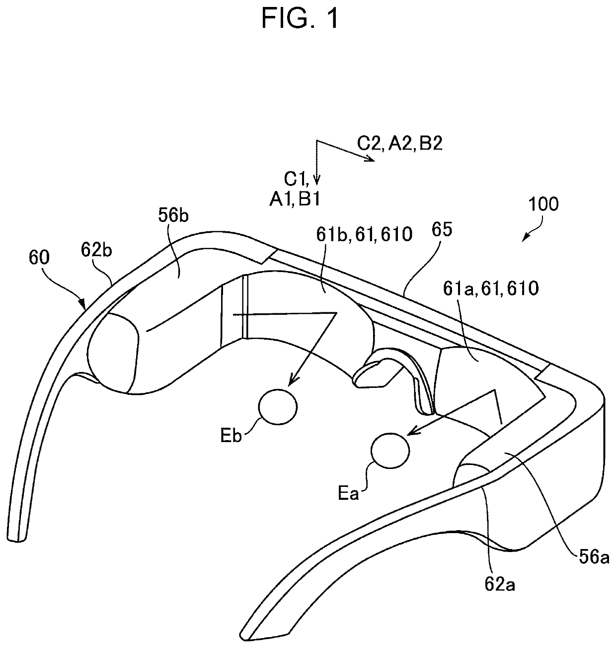
[0046]FIG. 1 is an external view illustrating an aspect of appearance of an image display device 100 to which the embodiment is applied.

[0047]In FIG. 1, the image display device 100 is a head-mount image display device and includes a right eye image light generation unit 56a, a right eye deflection member 61a configured to deflect image light emitted from the right eye image light generation unit 56a and make the image light incident on an observer's right eye Ea, a left eye image light generation unit 56b, and a left eye deflection member 61b configured to deflect the image light emitted from the left eye image light generation unit 56b and make the image light incident on an observer's left eye Eb. For example, the image display device 100 has a form resembling eyeglasses. Specifically, the image display device 100 includes a frame 60 configured to hold the right eye image light generation unit 56a, the right eye deflection member 61a, the left eye image light generation unit 56b,...

modification 1

[0075]In Modification 1, one mode of the first diffraction element 61 and the second diffraction element 31 will be described where image light represents a color image. Note that, the same constituents as those of Embodiment 1 are denoted by the same reference numerals, and repeated description thereof will be omitted. Furthermore, as in Embodiment 1, the first diffraction element 61 and the second diffraction element 31 have the same basic configuration, and therefore only a configuration of the first diffraction element 61 will be described here, and description of the second diffraction element 31 will be omitted.

[0076]FIG. 6 is a sectional view illustrating the first diffraction element 61 according to Modification 1. In Modification 1, the first diffraction element 61 includes reflective volume holographic elements 610R, 610G, and 610B which are stacked one on another, and the reflective volume holographic elements 610R, 610G, and 610B have interference fringes 611R, 611G, and...

modification 2

[0082]In Modification 2, another mode of the first diffraction element 61 and the second diffraction element 31 will be described where image light represents a color image. Note that, the same constituents as those of Embodiment 1 are denoted by the same reference numerals, and repeated description thereof will be omitted. Furthermore, as in Embodiment 1, the first diffraction element 61 and the second diffraction element 31 have the same basic configuration, and therefore only a configuration of the first diffraction element 61 will be described here, and description of the second diffraction element 31 will be omitted.

[0083]FIG. 8 is a sectional view illustrating the first diffraction element 61 according to Modification 2. In Modification 2, the first diffraction element 61 includes the reflective volume holographic element 610, and has a configuration in which the interference fringes 611R, 611G, and 611B are superimposed on one another.

[0084]As in Modification 1, each of the i...


PUM

PropertyMeasurementUnit
wavelengthaaaaaaaaaa

Abstract

An image display device includes an image light generation unit configured to generate image light, a projection system optical unit configured to project the image light, a correction system optical unit configured to correct aberrations, a first diffraction element configured to deflect the image light incident on a first incident surface, and a second diffraction element configured to deflect the image light incident on a second incident surface. The projection system optical unit, the second diffraction element, the correction system optical unit, and the first diffraction element are arranged in this order in a direction of the image light emitted from the image light generation unit, and the image light deflected and dispersed into rays of respective wavelengths by the second diffraction element is focused by the first diffraction element.

Description

BACKGROUND1. Technical Field[0001]The present disclosure relates to an image display device and a light guiding device.2. Related Art[0002]Devices using a diffraction element such as a holographic element include hologram recording / reproducing devices, and image display devices that cause image light to be incident on a user's eye by a diffraction element. An example of image display devices includes a head mount display (HMD) or the like mounted on an observer's head to direct an image to an observer's eye. In such an HMD, a holographic element is disposed in front of the observer's eye and functions to deflect image light to the observer's eye. In the holographic element, interference fringes are optimized to obtain an optimum diffraction angle and diffraction efficiency at a specific wavelength.[0003]For example, JP-A-2010-33026 discloses a HMD that uses a holographic element and proposes a display device having a configuration to guide image light by using a light guide plate an...

Claims


Application Information

Patent Timeline
Patent Type & Authority Patents(United States)
IPC IPC(8): G02B5/18G11B7/1392G11B7/1353G02B27/01G02B27/00G02B27/42G11B7/1372G11B7/00
CPCG11B7/1372G02B27/4238G02B27/0043G02B27/0103G11B7/1353G11B7/1392G02B27/0172G02B27/4211G11B2007/0003G02B2027/0178G02B27/4216G02B2027/0116G02B2027/011
Inventor NOGUCHI, TOSHIYUKI
Owner SEIKO EPSON CORP
Learn More