
Lighting system

Active Publication Date: 2020-02-18
CHICONY POWER TECH CO LTD
View PDF27 Cites 1 Cited by
  • Summary
  • Abstract
  • Description
  • Claims
  • Application Information

AI Technical Summary

Benefits of technology

The present invention is a lighting system that can control the lighting of individual or groups of lighting modules. This allows for greater flexibility and precision in the lighting needs of different areas.

Problems solved by technology

However, in the prior arts, different lamp functions of LED lights may require respective power sources for driving LEDs, which may cause the power supply of LED to have a larger volume, higher cost, and more electronic components, thus become a waste of resources.
In another aspect, when the LED lighting is changed from the usage of numerous LEDs to the usage of less LEDs (e.g., switched from high beam to low beam), the capacitor located at the output of the power converter will cause a peak current that is much greater than a steady-state current outputting to the LEDs due to the instantaneous voltage change of the capacitor and the continuous energy delivery of the power converter, thus result in an inrush current.
As a result, the electronic components are likely to be damaged owing to the impact of the inrush current.

Method used


Image

  • Lighting system
  • Lighting system
  • Lighting system

Examples


first embodiment

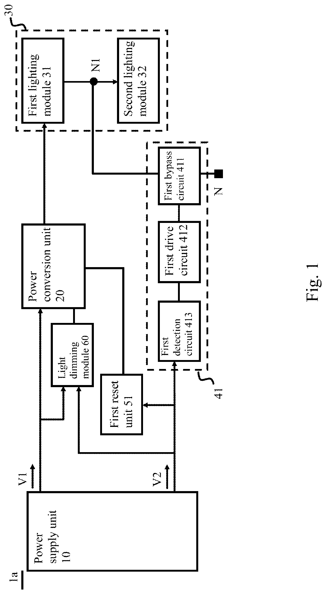
[0013]Hereinafter please first refer to FIG. 1 for an architecture diagram of a lighting system in the present invention. It should be noted that although the following uses the terms “first”, “second”, etc. to describe various components, these components should not be limited by the terms. The terms are used to distinguish one component from another. For example, without departing from the scope of the various described embodiments, the first lighting module may be referred to as a second lighting module, and similarly, the second lighting module may be referred to as a first lighting module. Similarly, the first lighting module and the second lighting module are both lighting modules, but they are not the same lighting module.

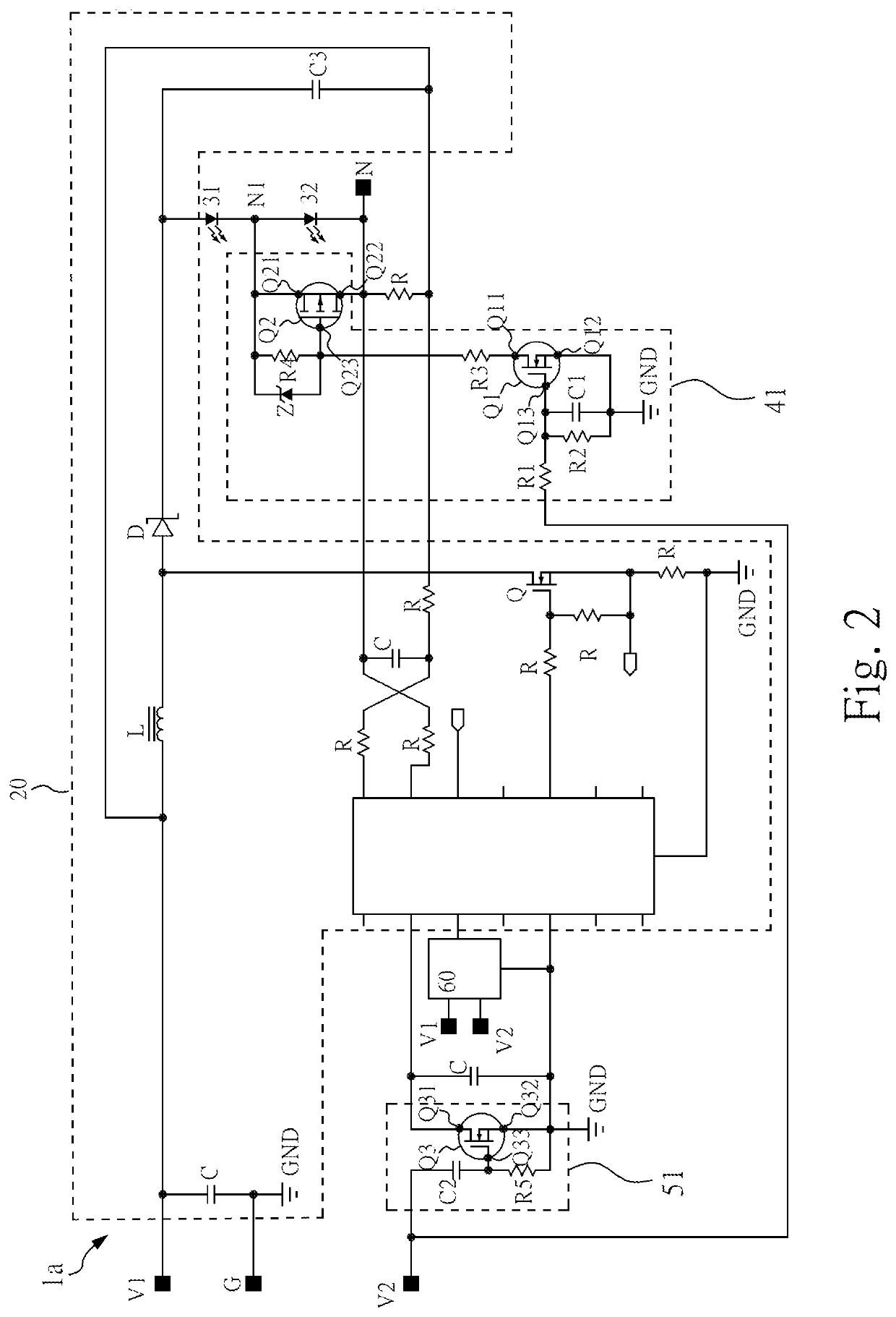
[0014]In the first embodiment of the present invention, the lighting system 1a includes a power supply unit 10, a power conversion unit 20, a lighting unit 30, a first switching unit 41, a first reset unit 51, and a light dimming module 60. The power supply ...

second embodiment

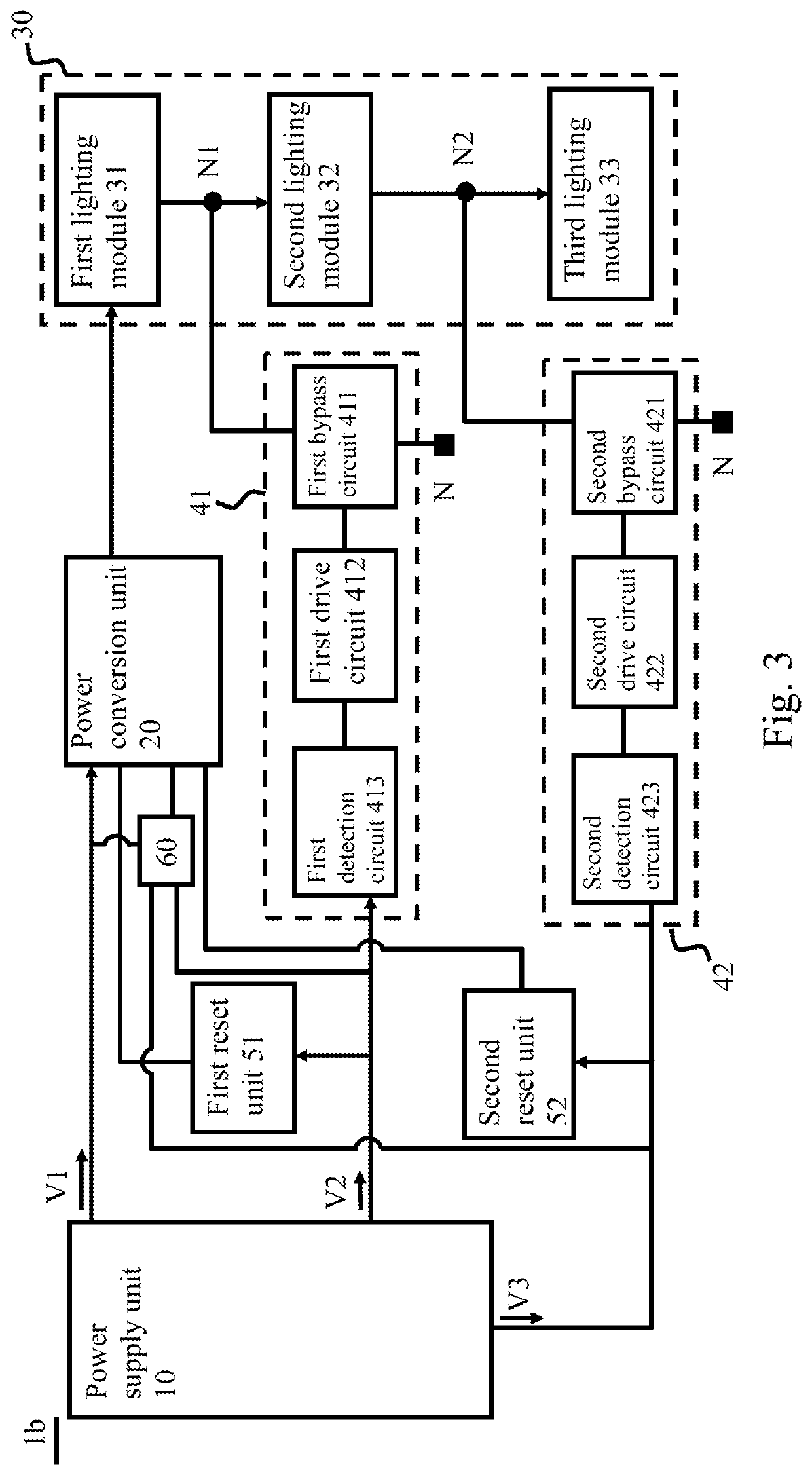
[0026]Then, please refer to FIG. 3 for a schematic diagram of a lighting system in the present invention.

[0027]The present invention does not limit the number of lighting modules in the lighting unit 30. In the second embodiment of the present invention, the lighting unit 30 of the lighting system 1b further includes a third lighting module 33. The third lighting module 33 is connected in series after the second lighting module 32. The power supply unit 10 further provides a third power signal V3. Additionally, the lighting system 1b further includes a second switching unit 42 and a second reset unit 52. The second switching unit 42 is electrically connected to the power supply unit 10 for receiving the third power signal V3, and electrically connected to a second node N2 between the second lighting module 32 and the third lighting module 33 to cause the third lighting module 33 to emit light or not according to the third power signal V3.

[0028]Further, the second switching unit 42 i...

third embodiment

[0031]Finally, please refer to FIG. 4 for a schematic diagram of a lighting system in the present invention.

[0032]In the third embodiment of the present invention, the third lighting module 33′ of the lighting system 1c is connected in series between the first lighting module 31 and the second lighting module 32. Particularly, the second switching unit 42′ is electrically connected to the power supply unit 10 for receiving the third power signal V3, and electrically connected to a second node N2′ between the first lighting module 31 and the third lighting module 33′ to enable the third lighting module 33′ to emit light or not according to the third power signal V3. The second switching unit 42′ includes a second bypass circuit 421′, a second drive circuit 422′ and a second detection circuit 423′. The second bypass circuit 421′ is electrically connected between the first node N1 and the second node N2′. The second drive circuit 422′ is electrically connected to the second bypass circ...


PUM


Abstract

A lighting system includes a power supply unit, a power conversion unit, a lighting unit, a first switching unit, and a first reset unit. The power supply unit is used to supply a first and a second power signal. The power conversion unit receives and converts the first power signal. According to the first power signal, a first lighting module of the lighting unit emits light. The first switching unit is connected to a first node between the first lighting module and a second lighting module for receiving the second power signal, so that the second lighting module emits light according to the second power signal. The first reset unit receives the second power signal; wherein when the second lighting module changes from lighting to no lighting, the first reset unit causes the power conversion unit to stop operating and then restart.

Description

BACKGROUND OF THE INVENTION[0001]1. Field of the Invention[0002]The present invention relates to a lighting system, particularly to a lighting system capable of controlling single or multiple lighting modules.[0003]2. Description of the Related Art[0004]The lighting system of today's vehicle contains various lamp functions such as daytime running light, low beam, high beam, turn signals, fog light and position light. Due to energy saving and styling requirements, various types of vehicle lights have gradually changed from halogen light to LED light. However, in the prior arts, different lamp functions of LED lights may require respective power sources for driving LEDs, which may cause the power supply of LED to have a larger volume, higher cost, and more electronic components, thus become a waste of resources. In another aspect, when the LED lighting is changed from the usage of numerous LEDs to the usage of less LEDs (e.g., switched from high beam to low beam), the capacitor locate...

Claims


Application Information

Patent Timeline
IPC IPC(8): H05B33/08H05B44/00
CPCH05B45/395H05B45/10H05B45/40H05B47/10H05B33/0815H05B45/37H05B47/17Y02B20/30
Inventor LIN, CHEN-CHI
Owner CHICONY POWER TECH CO LTD
Learn More