
Lighting apparatus

Active Publication Date: 2014-01-23
LG INNOTEK CO LTD
View PDF2 Cites 40 Cited by
  • Summary
  • Abstract
  • Description
  • Claims
  • Application Information

AI Technical Summary

Benefits of technology

The patent is for a lighting apparatus that can be easily controlled. It has a wireless communication function, allowing users to control the lighting through a wireless signal. This makes it much more convenient for users and improves the overall user experience.

Problems solved by technology

Accordingly, a user of the lighting apparatus must inconveniently control the lighting apparatus.

Method used


Image

  • Lighting apparatus
  • Lighting apparatus
  • Lighting apparatus

Examples


Embodiment Construction

[0013]Hereinafter, the embodiments will be described in detail with reference to accompanying drawings. In the accompanying drawings, the same components will be assigned with the same reference numerals. In a description of the embodiment, if the function or the structure related to the disclosure and generally known to those skilled in the art make the subject matter of the disclosure unclear, the details of the function or the structure will be omitted.

[0014]In the description of the embodiments, it will be understood that, when each element is referred to as being “on” or “under” another element, it can be “directly” or “indirectly” on or under another element or the other constituent elements may also be present. Such a position of the elements has been described with reference to the drawings.

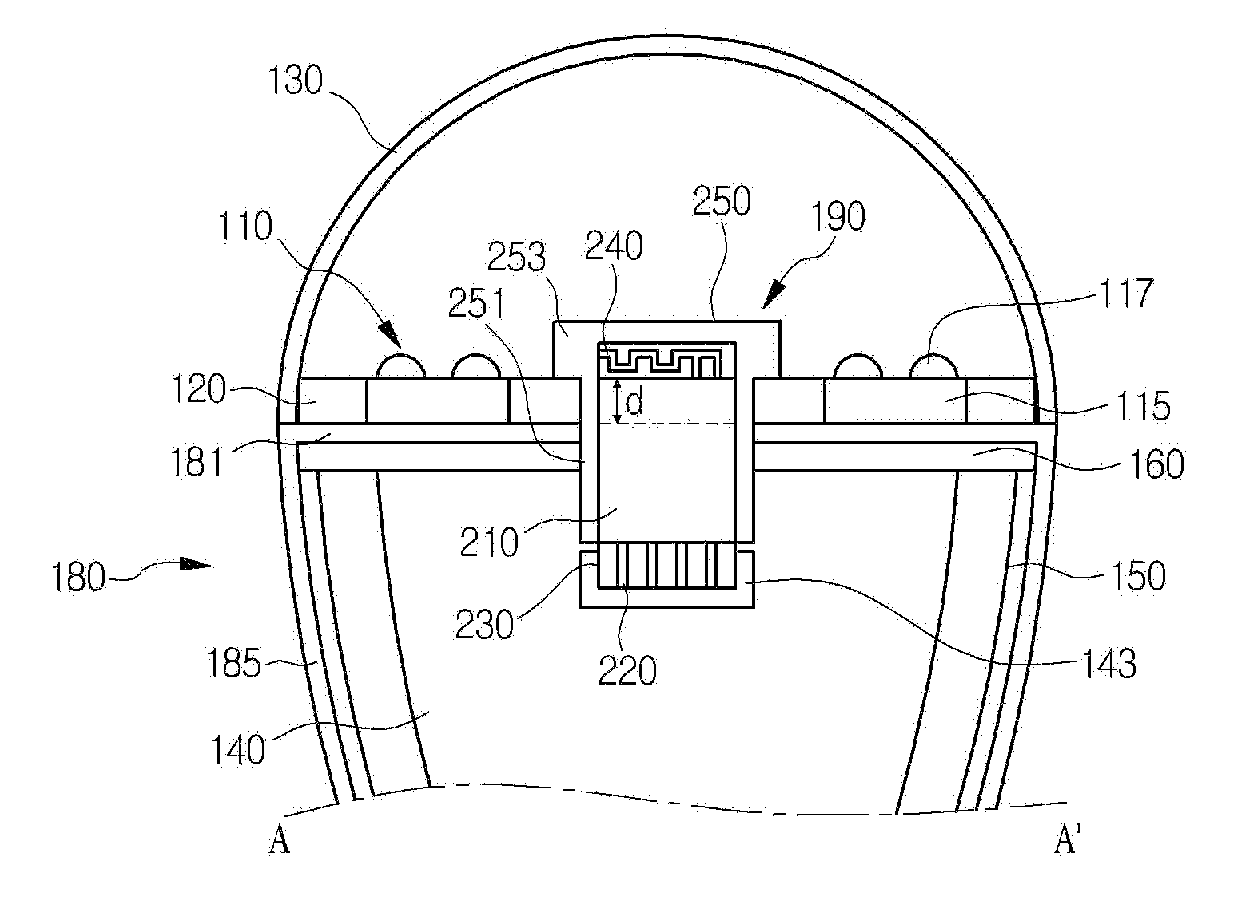
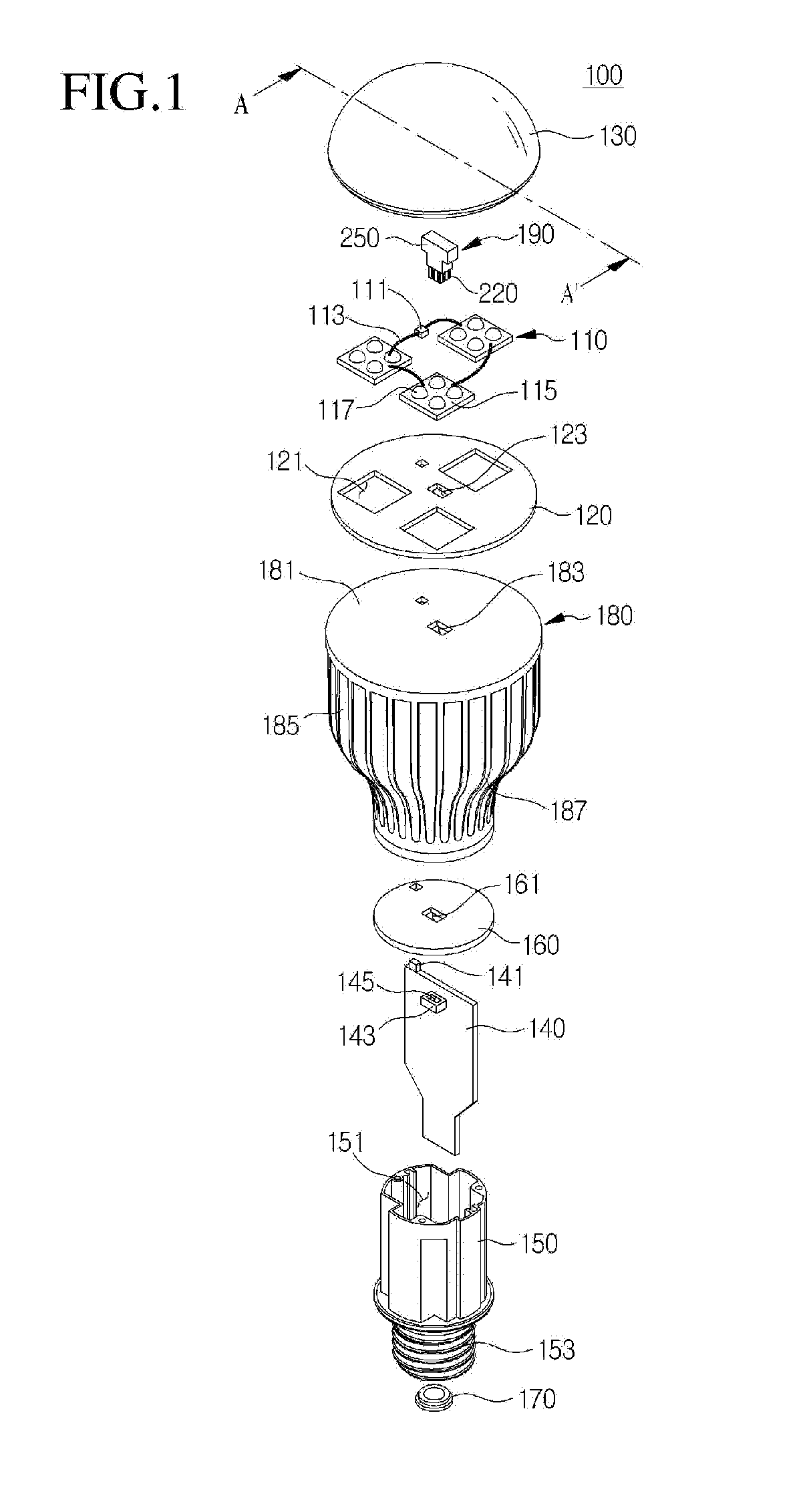
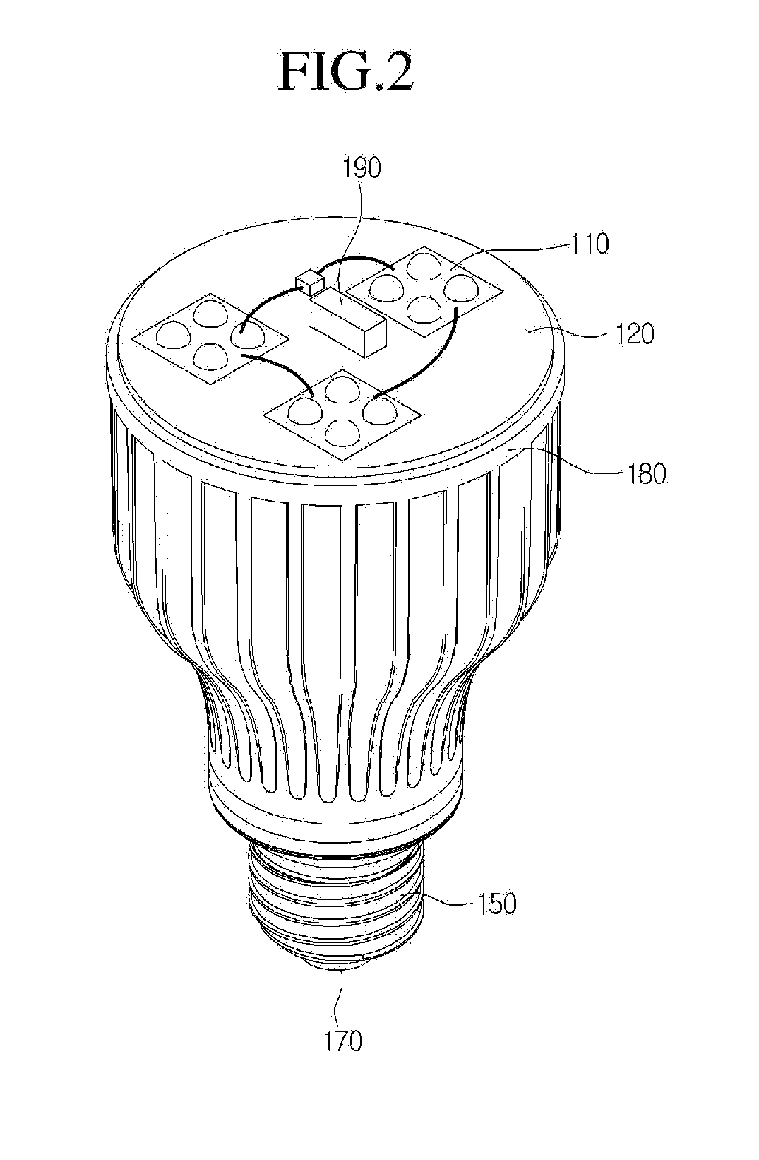
[0015]FIG. 1 is an exploded perspective view illustrating a lighting apparatus according to the embodiment, FIG. 2 is a perspective view illustrating a coupling structure of the lighting ...


PUM


Abstract

Disclosed is a lighting apparatus. The lighting apparatus includes: a control module supplying power; a heat sink receiving the control module; a light source mounted on the heat sink and connected to the control module; and a communication module including a connection terminal inserted into the heat sink and connected to the control module, and an antenna device protruding from the heat sink. Since the lighting apparatus can be controlled in a wireless scheme, a user of the lighting apparatus can easily control the lighting apparatus.

Description

CROSS-REFERENCE TO RELATED APPLICATION[0001]This application claims the benefit under 35 U.S.C. §119 of Korean Patent Application No. 10-2012-0079877, filed Jul. 23, 2012, which is hereby incorporated by reference in its entirety.BACKGROUND[0002]The embodiment relates to a lighting apparatus.[0003]In general, various types of lighting apparatuses such as ceiling-mounting type lamps, scenery lighting lamps, sleeping lamps, and stand lamps exist according to purposes thereof. The lighting apparatuses must irradiate light with sufficient luminance level according to purposes. Accordingly, recently, a light emitting diode (LED) has been used for a lighting apparatus. In comparison with other light sources such as a fluorescent lamp and an incandescent lamp, the LED is advantageous because of low power consumption, a long lifetime, a fast response time, safety, and environment-friendliness. Accordingly, many studies and researches to replace the existing light sources with the light emit...

Claims


Application Information

Patent Timeline
IPC IPC(8): H05B37/02H05B44/00
CPCH05B37/0272F21V23/0435F21V29/773F21K9/232F21Y2115/10F21V29/70F21V29/77F21V29/777H05B47/19H05B45/37F21V15/01F21V17/12F21V33/00Y02B20/30
Inventor CHUNG, WON SUK
Owner LG INNOTEK CO LTD
Learn More