Device and method for disruption detection

a technology of device and detection method, applied in the field of devices and detection methods, can solve problems such as affecting the normal operation of the device,

Active Publication Date: 2020-02-25
GAMBRO LUNDIA AB
View PDF13 Cites 8 Cited by
  • Summary
  • Abstract
  • Description
  • Claims
  • Application Information

AI Technical Summary

Problems solved by technology

A particularly serious condition may arise if the EC circuit is disrupted downstream of the blood pump while the blood pump is running, e.g. by the access device for blood reintroduction coming loose from the blood vessel access.
Such a venous-side disruption, which is commonly referred to as a Venous Needle Dislodgement (VND), may cause the subject to be drained of blood within minutes.
A disruption on the arterial side, e.g. by the access device for blood withdrawal coming loose from the blood vessel access, may also present a patient risk, by air being sucked into the EC circuit and transported into the cardiovascular system.
However, it may be difficult to set appropriate threshold values, since the average pressure in the EC circuit may vary between treatments and between subjects, and also during a treatment, e.g. as a result of the patient moving.
Further, if an access device comes loose and gets stuck in bed sheets or the patient's clothes, the measured average pressure might not change enough to indicate the potentially dangerous situation.
It may be a challenging task to remove e.g. the pump pulses, since the rate of the heart pulses and the rate of the blood pump, i.e. the blood flow through the EC circuit, may change over time.
Complete removal of the pump pulses is also rendered difficult by the fact that the pump pulses generally are much stronger than the heart and breathing pulses in the pressure signal.
An advanced filtering technique may thus be required, increasing complexity and potentially introducing stability and convergence issues.

Method used


Image

  • Device and method for disruption detection
  • Device and method for disruption detection
  • Device and method for disruption detection

Examples


Embodiment Construction

Throughout the description, the same reference numerals are used to identify corresponding elements.

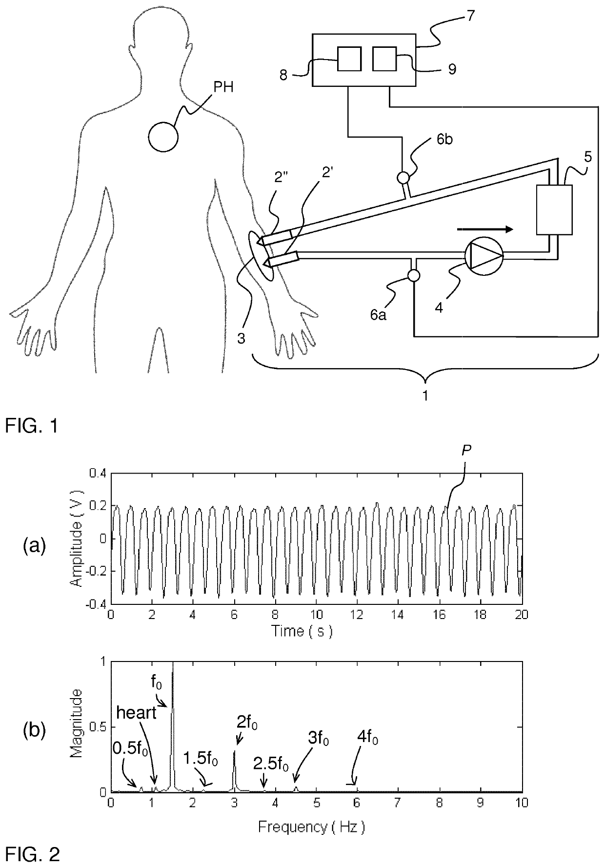
FIG. 1 illustrates a human subject which is connected to an extracorporeal fluid circuit 1 by way of access devices 2′, 2″ inserted into a dedicated vascular access 3 (also known as “blood vessel access”) on the subject. The extracorporeal fluid circuit 1 (denoted “EC circuit” in the following) is configured to communicate blood to and from the cardiovascular system of the subject. In one example, the EC circuit 1 is part of an apparatus for blood processing, such as a dialysis machine. In the illustrated example, a blood pump 4 draws blood from the vascular access 3 via access device 2′ and pumps the blood via blood lines (tubes) through a blood processing unit 5, e.g. a dialyzer, and back to the vascular access 3 via access device 2″. Thus, when both access devices 2′, 2″ are connected to the vascular access 3, the EC circuit 1 defines a blood path that starts and ends at the vascul...


PUM


Abstract

A monitoring device detects a disruption of a fluid connection between first and second fluid containing systems using one or more pressure sensors arranged in the first fluid containing system to detect first pulses from the first fluid containing system and second pulses from the second fluid containing system. The monitoring device receives (501) pressure signal(s) from the pressure sensor(s), populates (504) signal vectors by signal segments in the pressure signal(s) and computes (505) one or more eigenvectors and / or one or more eigenvalues for the signal vectors by a source separation algorithm. The monitoring device detects (506) the disruption based on a monitoring parameter, which is computed as a function of the eigenvector(s) and / or eigenvalue(s) to be responsive to the second pulses in the pressure signal(s). The monitoring device may be associated with or included in an apparatus for extracorporeal blood processing, such as a dialysis machine.

Description

PRIORITY CLAIMThe present application is a National Phase of International Application No. PCT / EP2016 / 062622, filed Jun. 3, 2016, which claims priority to Swedish Patent Application No. 1550884-9, filed Jun. 25, 2015, the entire contents of each of which are incorporated herein by reference and relied upon.TECHNICAL FIELDThe present invention relates to techniques for detecting a disruption of a fluid connection between a first fluid containing system comprising a first pulse generator and a second fluid containing system comprising a second pulse generator, by processing at least one pressure signal from a set of pressure sensors arranged in the first fluid containing system. The first fluid containing system may e.g. be an extracorporeal circuit for blood processing.BACKGROUND ARTIn extracorporeal blood processing, blood is taken out of a human subject, processed (e.g. treated) and then reintroduced into the subject by means of an extracorporeal blood flow circuit (“EC circuit”) w...

Claims


Application Information

Patent Timeline
Patent Type & Authority Patents(United States)
IPC IPC(8): A61M1/36A61B5/0215G16H40/63
CPCA61M1/3639A61M1/3656A61M2205/3331G16H40/63A61M2205/50A61M2205/18A61B5/0215A61B5/02152A61M2230/30
Inventor SOLEM, KRISTIANOLDE, BO
Owner GAMBRO LUNDIA AB
Why Eureka
Try Eureka