
Manually operated balancing weight dispenser

a technology of balancing weight and dispenser, which is applied in the direction of mechanical equipment, transportation and packaging, instruments, etc., can solve the problems of large waste of mass material, inability to afford high-performance automated balancing weight dispensing machines, and inability to maintain a large amount of machines, etc., and achieves precise balancing

Active Publication Date: 2020-02-25
WEGMANN AUTOMOTIVE GMBH
View PDF38 Cites 0 Cited by
  • Summary
  • Abstract
  • Description
  • Claims
  • Application Information

AI Technical Summary

Benefits of technology

The invention is a low-cost dispenser for balancing weights that can be manually operated and used with tires and rims of different masses. The dispenser uses a belt of balancing weights attached to a common tape carrier and stored in a storage space. The balancing weights are guided by a belt guide and a cutter is provided to cut the tape. The cutter is a simple module that can be easily replaced when the knife becomes blunt. The cutter has a solid base plate with a knife clamped, glued, welded, or soldered to it. The cutter has a cutting slot through which the balancing weights are inserted for cutting. The guide is designed to position the knife between adjacent balancing weights and prevent the knife from being blocked or damaged. The balancing weight dispenser can be mounted on a stand for easy access to the balancing weights. The cutter can also be enabled to cut the balancing weight body, allowing for more precise balancing.

Problems solved by technology

These balancing weights allow simple handling and storage, although the disadvantage is that a significant amount of the mass material is wasted.
A small tire workshop cannot afford a high performance automated balancing weight dispensing machine as described before.
These machines are too expensive and require a significant amount of maintenance.

Method used


Image

  • Manually operated balancing weight dispenser
  • Manually operated balancing weight dispenser
  • Manually operated balancing weight dispenser

Examples


Embodiment Construction

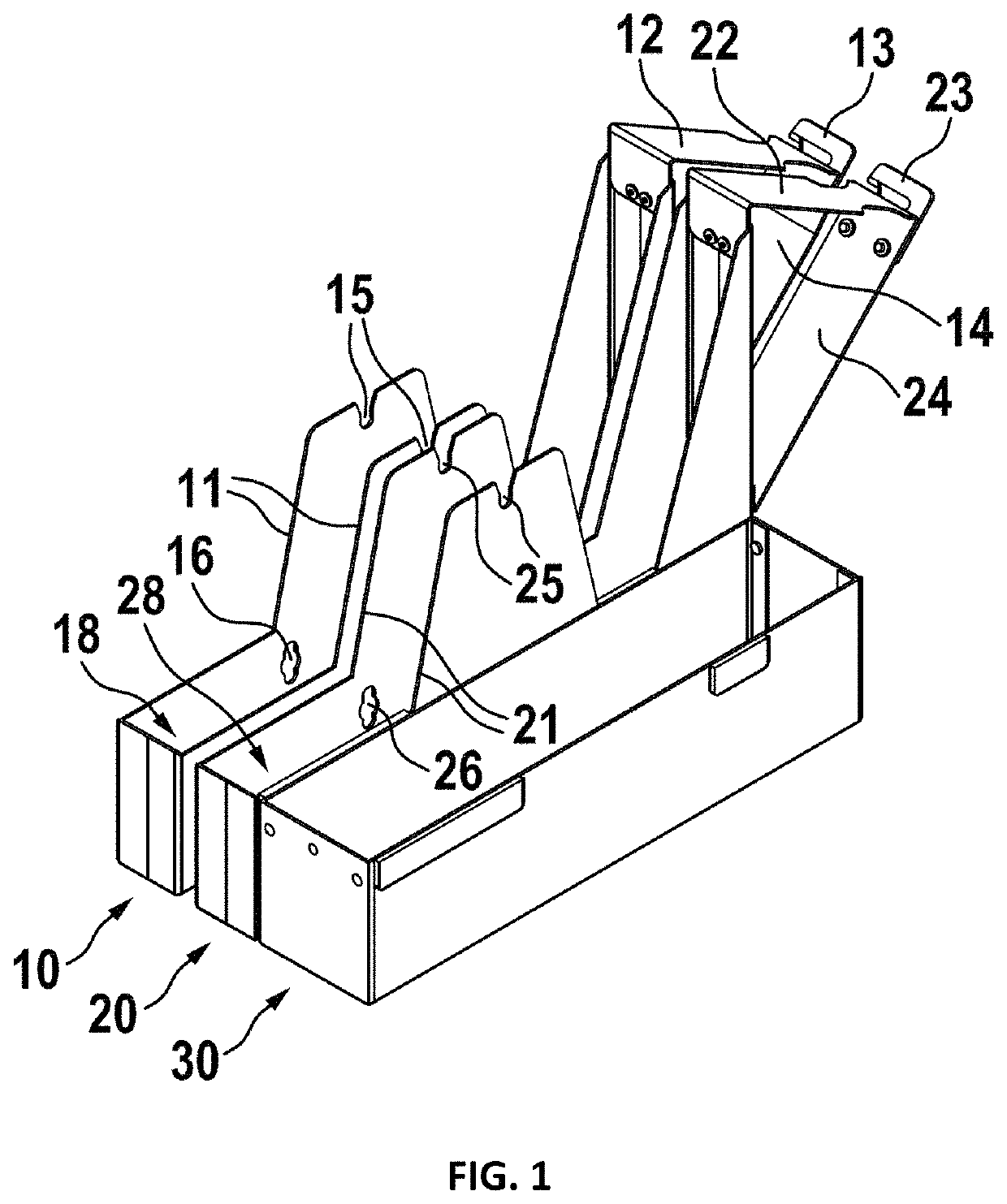
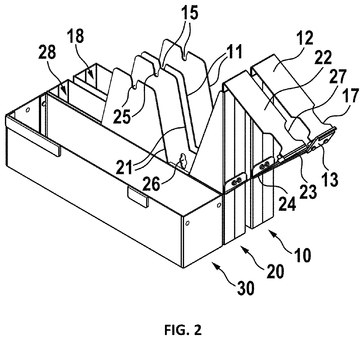
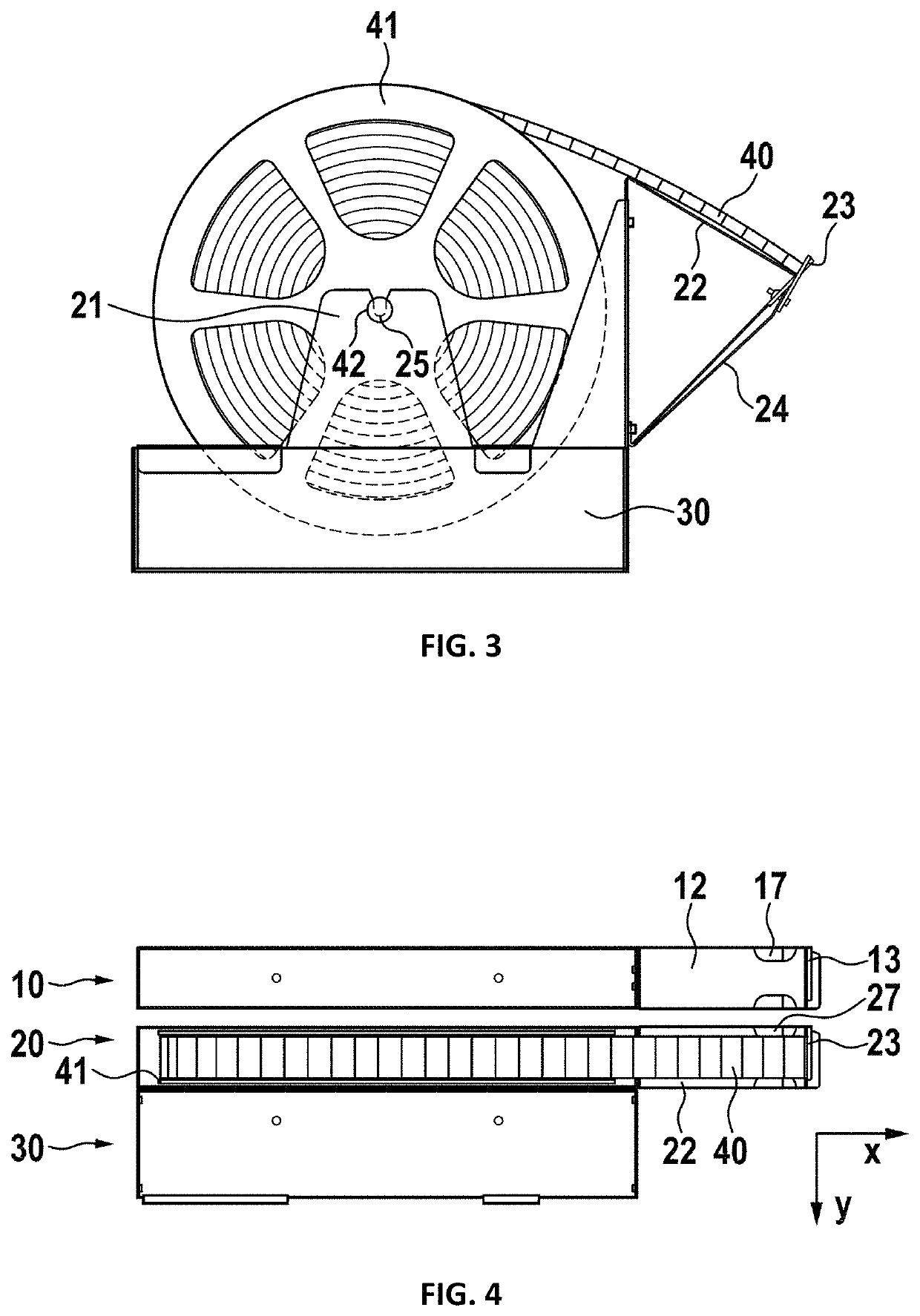
In FIG. 1, a balancing weight dispensing apparatus according to a first embodiment is shown. A first balancing weight dispenser 10, a second balancing weight dispenser 20, and a container 30 are assembled to a first balancing weight dispenser assembly. The first balancing weight dispenser 10 is basically the same as the second balancing weight dispenser 20. Therefore, only one balancing weight dispenser is described in more detail. For holding a reel 41, as later shown, a pair of reel holders 11, 21 is provided. Preferably, each reel holder has a pivot guide slot or hole 15, 25. For guiding the belt of balancing weights, a belt guide 12, 22 is provided. Furthermore, a cutter 13, 23 is provided and preferably arranged at the end of the belt guide 12, 22. For stabilizing the belt guide and holding the cutter in place, a support 14, 24 is provided. Although the embodiment is not limited to this simple design, a part of the body of the balancing weight dispenser together with the belt g...


PUM


Abstract

A balancing weight dispenser has a balancing weight storage space for storing a belt of balancing weights on a reel, a belt guide, and a cutter at one end of and / or along a length of the belt guide. The cutter comprises a knife, which is fixedly attached to the balancing weight dispenser. For delivery of a required amount of balancing weight mass, the belt of balancing weights is pulled from the reel until the desired number of balancing weights has been obtained. In the next step, the belt of balancing weights is cut, preferably between two adjacent balancing weights, to separate the selected portion of balancing weights from the remaining belt of balancing weights. The remaining belt falls back to the guide and remains in a desired position for receiving the next portion of balancing weights. This manually operated balancing weight dispenser can be provided at significantly lower costs compared to the automated high performance balancing weight dispensers as known from the prior art. It is very robust and has no serviceable parts.

Description

BACKGROUND OF THE INVENTION1. Field of the InventionThe invention relates to a manually operated dispensing device for balancing weights, preferably for balancing weights for vehicle wheels.2. Description of Relevant ArtSelf-adhesive balancing weights having a weight body, comprising a mass material and a self-adhesive tape for attaching the balancing weight to a rim are disclosed in EP 1 355 084 A1 and in EP 1 039 169 A1. The balancing weights are delivered in boxes, each box containing a plurality of balancing weights. The balancing weight bodies have segments, which allow cutting off or breaking off pieces of the balancing weight body, therefore reducing or modifying the mass of the balancing weight according to the required mass. These balancing weights allow simple handling and storage, although the disadvantage is that a significant amount of the mass material is wasted. If, for example, the total of mass of the balancing weight body is 60 grams, and only 25 grams are needed f...

Claims


Application Information

Patent Timeline
Patent Type & Authority Patents(United States)
IPC IPC(8): F16F15/32G01M1/32B65H35/06G01M1/02
CPCG01M1/326B65H35/06F16F15/328G01M1/02B60B15/28
Inventor HORNUNG, THOMASLUTZ, MICHAEL
Owner WEGMANN AUTOMOTIVE GMBH
Learn More