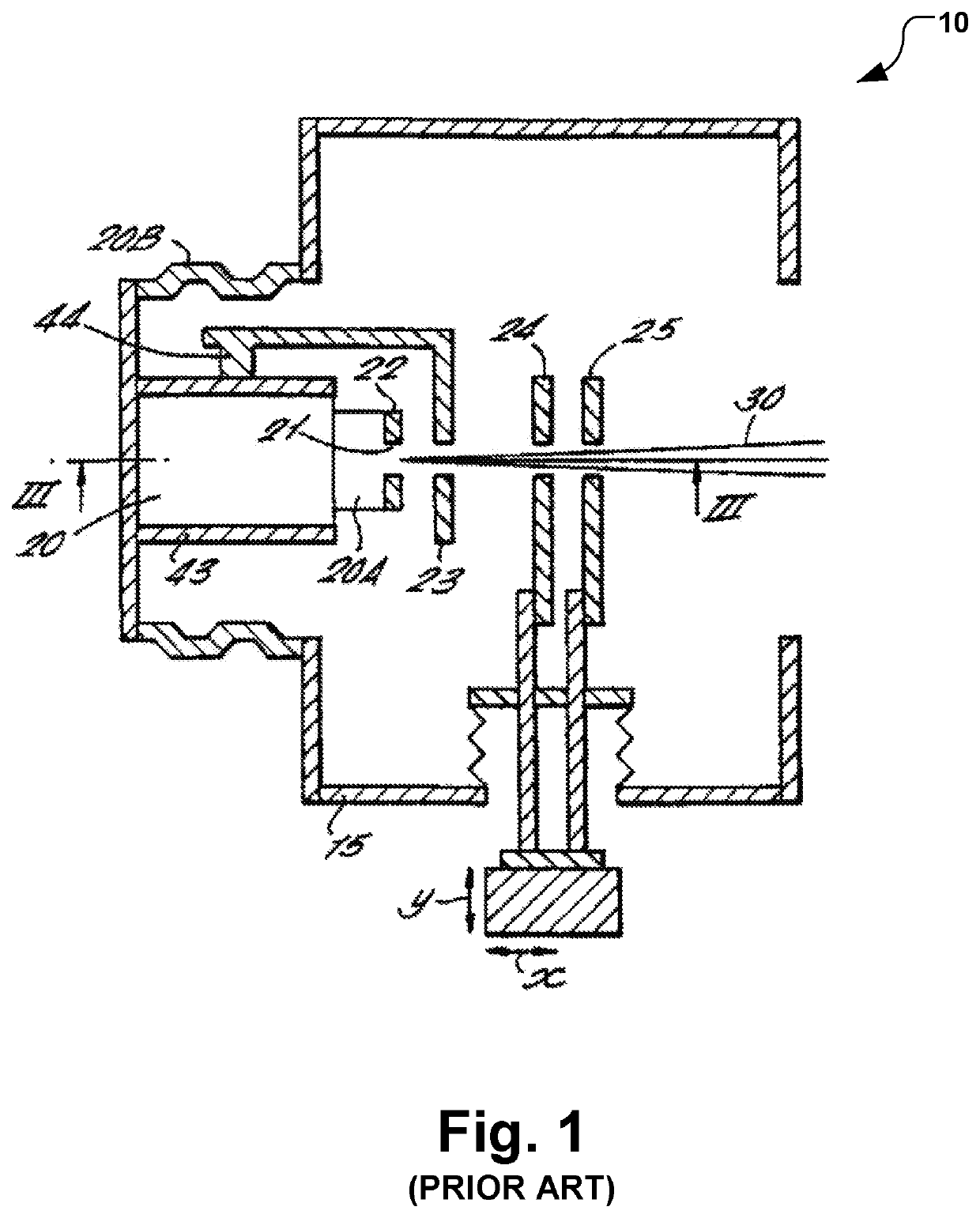
Tetrode extraction apparatus for ion source
a technology of extraction apparatus and ion source, which is applied in the direction of electrical apparatus, ion beam tubes, electric discharge tubes, etc., can solve the problems of difficulty in aligning all four apertures, ion beams will have a tendency to expand or “blow up”
- Summary
- Abstract
- Description
- Claims
- Application Information
AI Technical Summary
Benefits of technology
Problems solved by technology
Method used
Image

Examples
Embodiment Construction
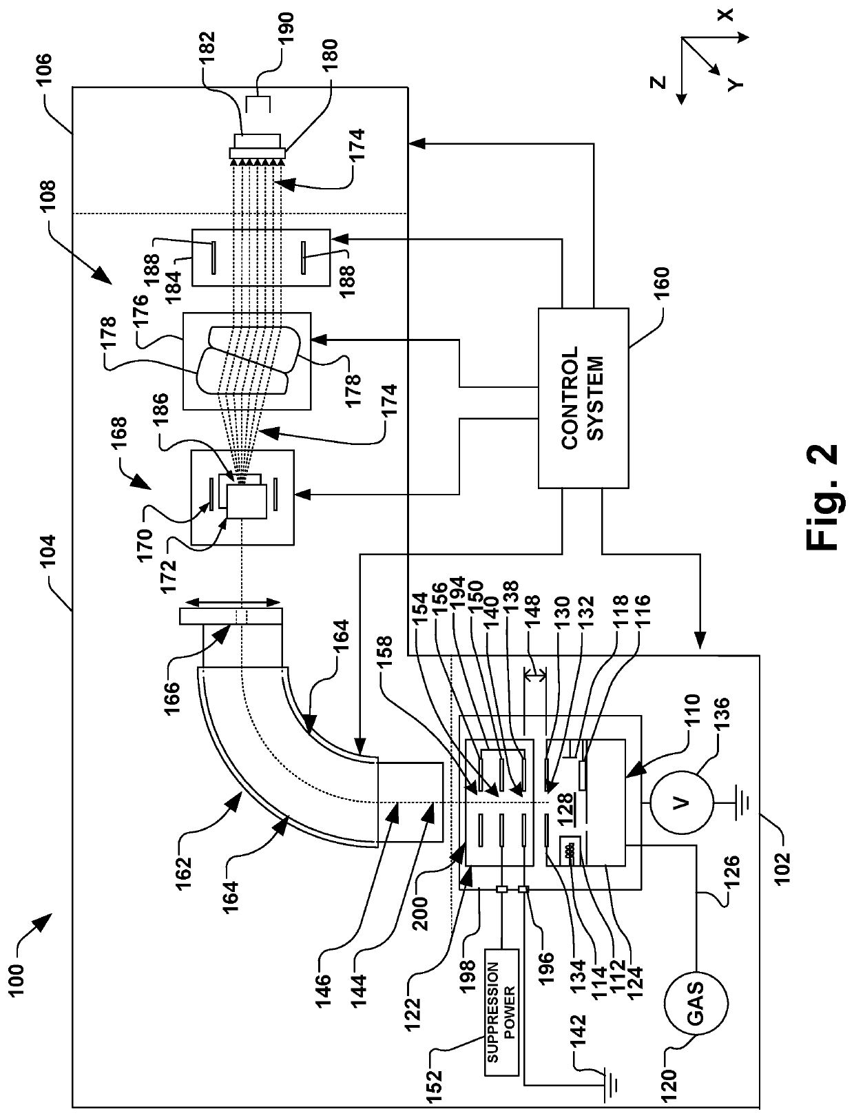
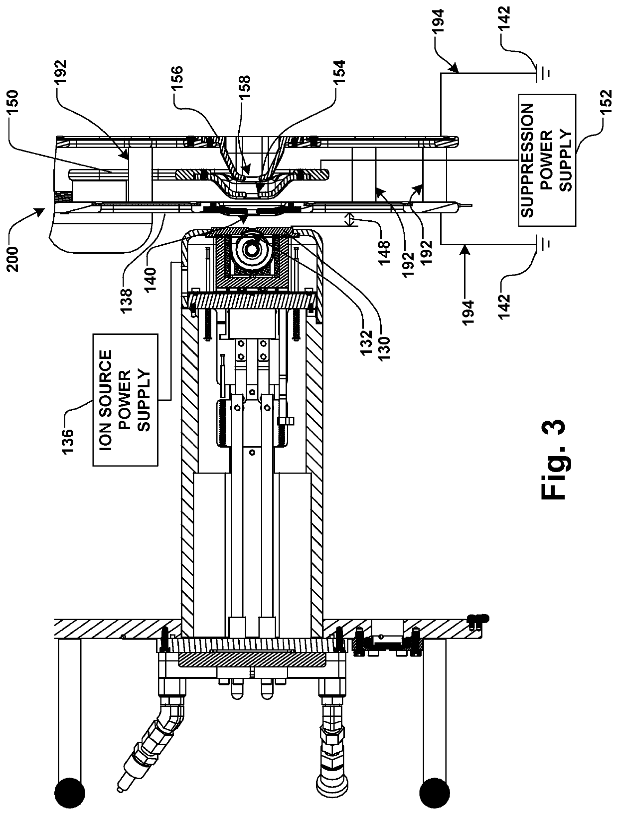
The present invention is directed generally towards an improved ion extraction electrode apparatus, system, and method for use in an ion implantation system. Accordingly, the present invention will now be described with reference to the drawings, wherein like reference numerals may be used to refer to like elements throughout. It is to be understood that the description of these aspects are merely illustrative and that they should not be interpreted in a limiting sense. In the following description, for purposes of explanation, numerous specific details are set forth in order to provide a thorough understanding of the present invention. It will be evident to one skilled in the art, however, that the present invention may be practiced without these specific details. Further, the scope of the invention is not intended to be limited by the embodiments or examples described hereinafter with reference to the accompanying drawings, but is intended to be only limited by the appended claims...
PUM
 Abstract
Description
Claims
Application Information
 - R&D Engineer
- R&D Manager
- IP Professional
- Industry Leading Data Capabilities
- Powerful AI technology
- Patent DNA Extraction
Browse by: Latest US Patents, China's latest patents, Technical Efficacy Thesaurus, Application Domain, Technology Topic.
© 2024 PatSnap. All rights reserved.Legal|Privacy policy|Modern Slavery Act Transparency Statement|Sitemap