
Method and apparatus for producing forging by rotary forging

a technology of rotary forging and forging equipment, which is applied in the direction of forging presses, forging/pressing/hammering equipment, handling devices, etc., can solve the problems of increasing the weight of the die itself, increasing the cost of producing difficulty in actually employing such a rotary forging apparatus, etc., to achieve efficient rotary forging, easy to rotate, and easy to use

Active Publication Date: 2020-03-03
HITACHI METALS LTD
View PDF21 Cites 0 Cited by
  • Summary
  • Abstract
  • Description
  • Claims
  • Application Information

AI Technical Summary

Benefits of technology

The present invention provides a method and apparatus for rotary forging that can easily rotate large-size materials without damaging them or hindering the rotation caused by pressing surfaces. This results in efficient forging and enables the use of large-scale materials without the need for a large-scale rotary mechanism. Additionally, the invention prevents friction between the material to be forged and the lower die, which can cause the material to rotate irregularly. This separation between the material and the lower die allows for easier and safer forging.

Problems solved by technology

However, in the example discussed in JP 2009-012059 A, in rotatingly forging a large material to be forged, it is necessary to use a large die for both the upper die and the lower die, and thus the weight of the dies themselves may increase.
If a rotary mechanism is to be arranged in either of an upper die or a lower die, an extremely large mechanism may become necessary in terms of its design, and thus the costs for producing a rotary forging apparatus may increase.
Therefore, it is difficult to actually employ such a rotary forging apparatus.
However, if a large material to be forged is used, high frictional force may be applied between the material to be forged and the surface of the lower die on which the material to be forged is placed.
Accordingly, if rotational force is externally applied to the material to be forged, it is not easy to rotate the material to be forged by a predetermined angle, control the rotation angle, and stop it at a correct location.
In addition, if a material to be forged is to be forcibly rotated by applying a high rotational force, unintended plastic deformation may occur in a portion to which the rotational force has been applied and the material to be forged may be cracked in the circumferential direction.
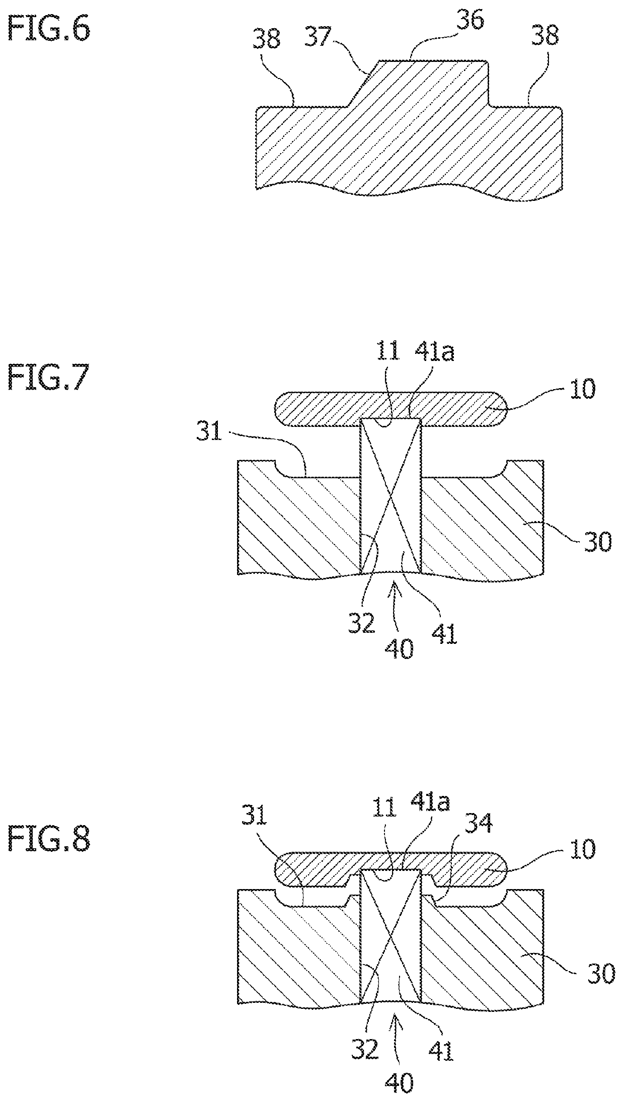
However, in this case, a part of the material to be forged on the side of the lower die may intrude between the pressing surfaces of the lower die during forging.

Method used


Image

  • Method and apparatus for producing forging by rotary forging
  • Method and apparatus for producing forging by rotary forging
  • Method and apparatus for producing forging by rotary forging

Examples


Embodiment Construction

[0021]Embodiments of a rotary forging method and a rotary forging apparatus according to the present invention will be described in detail below with reference to attached drawings. The present invention is not limited to the embodiments described below.

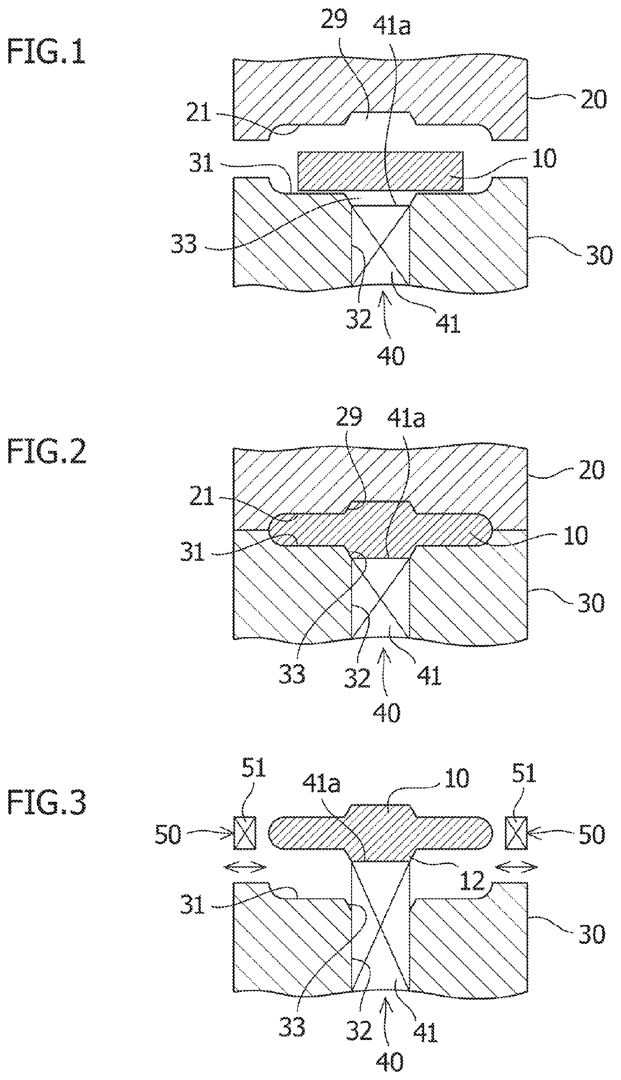
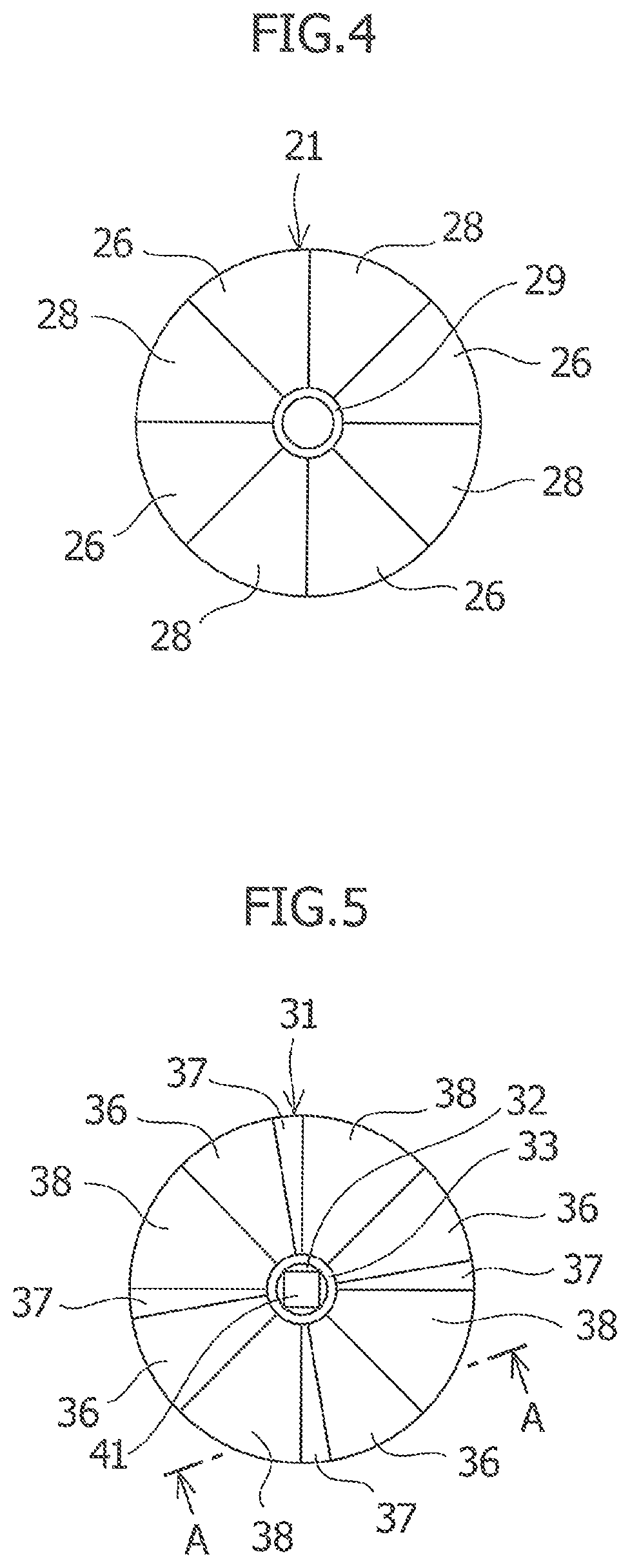
[0022]An embodiment of the rotary forging apparatus according to the present invention will be described with reference to FIGS. 1 to 4. As shown in FIGS. 1 to 4, a rotary forging apparatus according to the present embodiment includes, at least: an upper die 20 including a pressing surface 26 for pressing the material 10 to be forged; a lower die 30 on which the material 10 to be forged can be placed; an elevation device 40 configured to separate the material 10 to be forged from the lower die 30 and place the material 10 to be forged on the lower die 30; and a rotation device 50 configured to rotate the material 10 to be forged in a state in which the material 10 to be forged is separated from the lower die 30.

[0023]As shown in FIG....


PUM

PropertyMeasurementUnit
shapeaaaaaaaaaa
weightaaaaaaaaaa
angleaaaaaaaaaa

Abstract

A cycle is repeated a plurality of times, which includes a forging process for placing a material to be forged in a lower die and pressing the material to be forged in this state and then separating an upper die from the material to be forged; an elevation process for lifting the material to be forged by using an elevation device to separate the material to be forged from the lower die; a rotation process for rotating the material to be forged around its center by using a rotation device; and a lowering process for placing the material to be forged rotated by the elevation device in the lower die.

Description

CROSS-REFERENCES TO RELATED APPLICATIONS[0001]This application claims priority from Japanese Patent Application No. 2015-200479 filed on Oct. 8, 2015, which is incorporated herein by reference in its entirety.TECHNICAL FIELD[0002]The present invention relates to a method and an apparatus for producing a forging by rotary forging.BACKGROUND ART[0003]Rotary forging has been conventionally known as a technique for hot-forging a disk-shaped material to be forged. For example, JP 2009-012059 A discloses a method in which a rotary forging apparatus including upper and lower dies is used, the apparatus holds a material to be forged on top and bottom surfaces of the material and presses the material to perform forging, the upper die is then separated and rotated, the upper die is then pressed onto the top surface of the material to be forged again, and the above series of operations is repeated to perform hot forging.SUMMARY OF INVENTION[0004]However, in the example discussed in JP 2009-012...

Claims


Application Information

Patent Timeline
Patent Type & Authority Patents(United States)
IPC IPC(8): B21J13/12B21J5/00B21J13/00B21J5/02B21K1/32B21J13/14B21J9/02B21J9/18B21K27/00
CPCB21J5/008B21J13/12B21J5/02B21J13/00B21K1/32B21J5/025B21K27/00B21J9/025B21J13/14B21J9/18
Inventor SHIMOHIRA, EIJISATOFUKUI, TSUYOSHI
Owner HITACHI METALS LTD
Learn More