Flyback converter with multiplier signal control circuit and method

a technology of multiplier signal and converter, applied in the direction of electric variable regulation, process and machine control, instruments, etc., can solve the problems of lower power factor and greater thd, and achieve the effect of reducing the total harmonic distortion (thd) of the input current and improving the power factor of flyback converter

Active Publication Date: 2020-03-03
UNIVERSAL LIGHTING TECHNOLOGIES
View PDF9 Cites 3 Cited by
  • Summary
  • Abstract
  • Description
  • Claims
  • Application Information

AI Technical Summary

Benefits of technology

[0011]A need exists for improving (increasing) the power factor of a flyback type PFC converter by reducing the total harmonic distortion (THD) of the input current. As described herein,

Problems solved by technology

Table I illustrates that a lower power factor and greater THD is a drawback for usi

Method used


Image

  • Flyback converter with multiplier signal control circuit and method
  • Flyback converter with multiplier signal control circuit and method
  • Flyback converter with multiplier signal control circuit and method

Examples


first embodiment

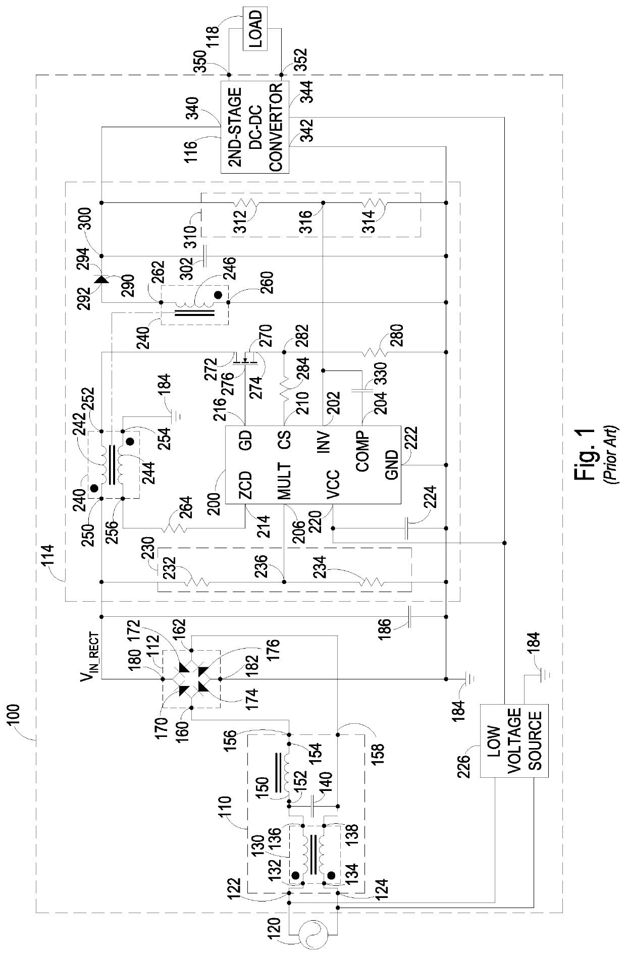
[0096]FIG. 4 illustrates an improved two-stage electronic switching power supply 500 in accordance with the present disclosure. The improved two-stage electronic switching power supply 500 improves the power factor and THD of the PFC circuit 114. The improved two-stage electronic switching power supply of FIG. 4 is similar to the previously described two-stage electronic switching power supply 100 of FIG. 1 and like elements are numbered the same as in FIG. 1. Unlike the previously described two-stage electronic switching power supply of FIG. 1, the improved two-stage electronic switching power supply of FIG. 4 includes an improved power factor correction (PFC) circuit 504 that includes an improved multiplier circuit 510.

[0097]The improved multiplier circuit 510 is coupled across the rectifier output filter capacitor 186 between the positive voltage output terminal 180 of the rectifier 112 and the local circuit ground connection 184, and to the multiplier (MULT) input 206 of the PFC...

second embodiment

[0115]FIG. 6 illustrates an improved two-stage electronic switching power 600 in accordance with the present disclosure. The improved two-stage electronic switching power supply 600 improves the power factor and THD of the PFC circuit 114. The improved two-stage electronic switching power supply of FIG. 6 is similar to the previously described two-stage electronic switching power supply 100 of FIG. 1 and like elements are numbered the same as in FIG. 1. Unlike the previously described two-stage electronic switching power supply of FIG. 1, the improved two-stage electronic switching power supply of FIG. 6 includes an improved power factor correction (PFC) circuit 604 that has an improved multiplier circuit 610.

[0116]The improved multiplier circuit 610 is coupled across the rectifier output filter capacitor 186 between the positive voltage output terminal 180 of the rectifier 112 and the local circuit ground connection 184, and to the multiplier (MULT) input 206 of the PFC IC 200. The...

third embodiment

[0119]FIG. 7 illustrates an improved two-stage electronic switching power 700 in accordance with the present disclosure. The improved two-stage electronic switching power supply 700 improves the power factor and THD of the PFC circuit 114. The improved two-stage electronic switching power supply of FIG. 7 is similar to the previously described two-stage electronic switching power supply 100 of FIG. 1 and like elements are numbered the same as in FIG. 1. Unlike the previously described two-stage electronic switching power supply of FIG. 1, the improved two-stage electronic switching power supply of FIG. 7 includes an improved power factor correction (PFC) circuit 704 that has an improved multiplier circuit 710.

[0120]The new multiplier circuit 710 is coupled across the rectifier output filter capacitor 186 between the positive voltage output terminal 180 of the rectifier 112 and the local circuit ground connection 184, and to the multiplier (MULT) input 206 of the PFC IC 200. The mult...


PUM


Abstract

A multiplier signal, and multiplier circuits and methods are provided to improve the total harmonic distortion (THD) and power factor (PF) for a flyback type power factor correction (PFC) circuit. The multiplier signal has a “pulled-up” waveshape that is configured to compensate for the “push-down” effect of varying off times of an electronic switch of the PFC on a line current of the PFC. The multiplier circuit is configured to reduce the multiplier signal during a first operational mode of the multiplier circuit and is further configured to maintain a typical multiplier signal during a second operational mode. The first operational mode occurs before a first phase angle and after a second phase angle during each half-cycle of a power source coupled to the PFC circuit. The second operational mode occurs between the first and second phase angles during each half-cycle.

Description

CROSS-REFERENCES TO RELATED APPLICATIONS[0001]This application claims benefit under 35 USC. § 119(e) of U.S. Provisional Patent Application No. 62 / 678,357, filed May 31, 2018, entitled “Flyback Converter with Multiplier Control Circuit and Method.”[0002]A portion of the disclosure of this patent document contains material that is subject to copyright protection. The copyright owner has no objection to the reproduction of the patent document or the patent disclosure, as it appears in the U.S. Patent and Trademark Office patent file or records, but otherwise reserves all copyright rights whatsoever.FIELD OF THE INVENTION[0003]The present disclosure relates generally to two-stage power supply circuits having a power factor correction circuit as a first stage and a DC-DC converter as a second stage. More particularly, the disclosure pertains a portion of the power factor correction circuit referred to herein as a multiplier circuit.BACKGROUND[0004]A typical power supply circuit receives...

Claims


Application Information

Patent Timeline
IPC IPC(8): H02M1/42H02M1/00H02M3/335
CPCH02M1/0061H02M3/3353H02M1/4208H02M2001/0003H02M1/4258H02M1/0003Y02B70/10
Inventor XIONG, WEI
Owner UNIVERSAL LIGHTING TECHNOLOGIES
Why Eureka
Try Eureka