Array of acoustical returner devices to reflect sound back in the incident direction

a technology of acoustical returner and incident direction, which is applied in the direction of sound producing devices, instruments, etc., can solve the problems of reducing the signal to noise (snr) value, degrading speech intelligibility, and masking of high-frequency consonants by low-frequency vowel sounds, so as to reduce the self-made sound and increase the volume

Active Publication Date: 2020-03-10
RPG ACOUSTICAL SYST LLC
View PDF9 Cites 5 Cited by
  • Summary
  • Abstract
  • Description
  • Claims
  • Application Information

AI Technical Summary

Benefits of technology

[0005](2) In an important aspect, the present invention is designed to filter out the frequencies which do not contribute to and can mask the understanding of speech (referred to as speech intelligibility). The power of speech is delivered in the vowels (a, e, i, o, u and sometimes y) which are predominantly in the frequency range of 250 Hz to 500 Hz. More importantly, speech intelligibility is delivered in the consonants (b, c, d, f, g, h, j, k, l, m, n, p, q, r, s, t, v, w), which requires information at 2,000 Hz to 6,000 Hz and above. If the frequencies at 500 Hz and below predominate, due to excessive reverberation, for example, these frequencies can mask the consonants and corrupt intelligibility. In addition, typical treatments of absorbing material on the ceiling of the room, in the form of typical ceiling tiles or fabric wrapped panels, may excessively reduce the high-frequency consonant sounds and result in the masking of high-frequency consonants by low-frequency vowel sounds. Simply adding large amounts of high frequency absorption to the room to achieve short reverberation times also leads to reduced Signal to Noise (SNR) values and degraded speech intelligibility, due to reduced sound levels. The ceiling area is very important to provide useful early reflections. Therefore, this invention describes a method to not only filter the voice frequencies to enhance speech intelligibility, but also redirects the important early reflections back to their source, which improves the signal-to-noise ratio (SNR) and speech intelligibility, to provide passive amplification and reduce interference to neighboring locations.
[0008](5) Examples of environments of use for the present invention are an office setting or nursing station in which a large room is divided up into spaces or cubicles by partitions. Acoustical returners in accordance with the teachings of the present invention can be mounted above each space or cubicle, for example, in ceiling mounted arrays or clouds above each space or cubicle. A person within the space or cubicle speaking on the phone or with others will have his or her words returned back to them and passively amplified with extraneous sounds filtered out. In this way, the speaker will hear his or her words loudly and this will encourage them to speak more softly so as not to disrupt workers in adjacent spaces or cubicles.
[0013](10) It is a further object of the present invention to utilize this multi-element array in applications in which benefit from this unique “boomerang” capability, like an office or teleconference environment in which the redirected sound to the speaker will passively amplify their speech and encourage them to lower their voice, thus creating less of a noise disturbance to nearby workers.
[0015](12) It is a further object of the present invention to take advantage of the psychoacoustic effect of reducing self-made sound by passively increasing its volume to the source, e.g., a practicing instrumentalist or vocalist can hear oneself more clearly when the emitted sound is returned rather than scattered or absorbed.

Problems solved by technology

(1) In a first aspect, the present invention contemplates the use of tri-rectangular tetrahedrons or corner reflectors connected in an array in order to reflect sound waves back to their source.
(2) In an important aspect, the present invention is designed to filter out the frequencies which do not contribute to and can mask the understanding of speech (referred to as speech intelligibility). The power of speech is delivered in the vowels (a, e, i, o, u and sometimes y) which are predominantly in the frequency range of 250 Hz to 500 Hz. More importantly, speech intelligibility is delivered in the consonants (b, c, d, f, g, h, j, k, l, m, n, p, q, r, s, t, v, w), which requires information at 2,000 Hz to 6,000 Hz and above. If the frequencies at 500 Hz and below predominate, due to excessive reverberation, for example, these frequencies can mask the consonants and corrupt intelligibility. In addition, typical treatments of absorbing material on the ceiling of the room, in the form of typical ceiling tiles or fabric wrapped panels, may excessively reduce the high-frequency consonant sounds and result in the masking of high-frequency consonants by low-frequency vowel sounds. Simply adding large amounts of high frequency absorption to the room to achieve short reverberation times also leads to reduced Signal to Noise (SNR) values and degraded speech intelligibility, due to reduced sound levels. The ceiling area is very important to provide useful early reflections. Therefore, this invention describes a method to not only filter the voice frequencies to enhance speech intelligibility, but also redirects the important early reflections back to their source, which improves the signal-to-noise ratio (SNR) and speech intelligibility, to provide passive amplification and reduce interference to neighboring locations.
(3) There are numerous ways in which frequencies outside a desired range can be filtered. For example, an array of acoustical returners in accordance with the teachings of the present invention can be combined with sound absorbers to absorb frequencies the user does not want to have returned to the source. One example of such absorbers consists of rendering the returners somewhat porous so that sound waves below the desired frequency range can travel through the porosity and into an absorbing area which may include fiberglass or other sound absorbing fabrics.

Method used


Image

  • Array of acoustical returner devices to reflect sound back in the incident direction
  • Array of acoustical returner devices to reflect sound back in the incident direction
  • Array of acoustical returner devices to reflect sound back in the incident direction

Examples


Embodiment Construction

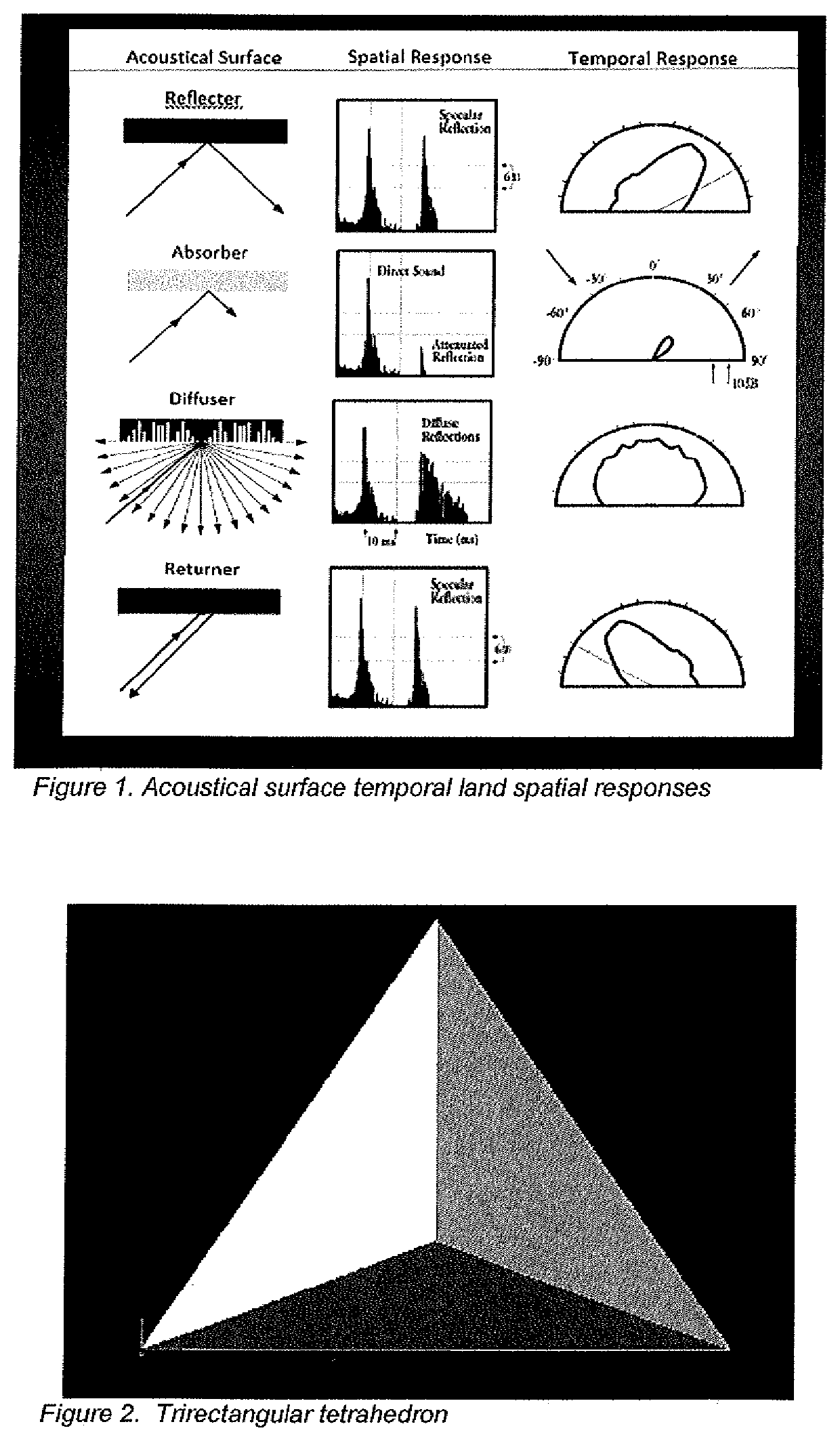
[0034]With reference first to FIG. 1, a chart is shown which provides the spatial response and temporal response for four types of acoustical treatments. Those types are reflectors, absorbers, diffusers, and returners. As seen in FIG. 1, in a reflector, incident sound is reflected forward at an angle corresponding to the angle of incidence. The ideal reflector reflects as much of the sound as is possible. In an absorber, a percentage of the incident sound is absorbed by the absorber so that sound emanating from the absorber is reduced particularly in amplitude. A diffuser takes incident sound and diffuses it, preferably uniformly about a listening room. A returner returns the sound back to its source. The present invention is concerned with returners.

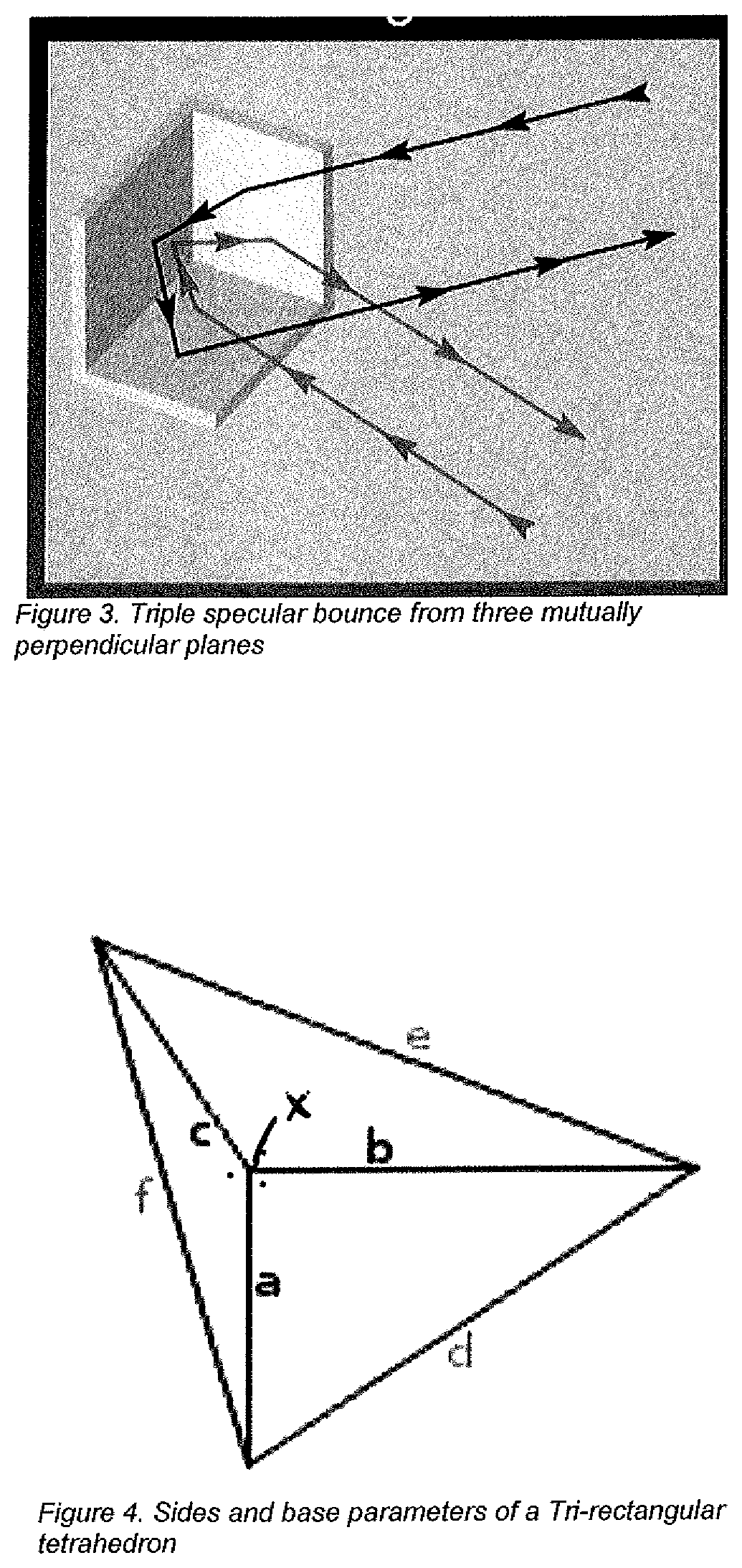
[0035]FIG. 2 shows a front view of a tri-rectangular tetrahedron. As shown in FIG. 2, such a device is made up of walls having three mutually perpendicular surfaces. In FIG. 2, those surfaces consist of triangles.

[0036]With reference to...


PUM


Abstract

A plurality of tri-rectangular tetrahedrons are mounted in an array to reflect sound waves back to their source. The array filters out the acoustic range below the normal range of frequencies for the spoken voice. The array is combined with a sound absorber to absorb frequencies the user does not want to have returned to the source. One example of such absorbers consists of rendering the returner somewhat porous with microperforations or microslits so that sound waves below the desired frequency range can travel through the porosity and into an absorbing area which may include fiberglass or other sound absorbing fabrics. Examples of environments of use for the present invention are an office setting or nursing station in which a large room is divided up into spaces or cubicles by partitions. Acoustical returners can be mounted above each space or cubicle, for example, in ceiling mounted arrays or clouds above each space or cubicle.

Description

BACKGROUND OF THE INVENTION[0001]The present invention relates to an array of acoustical returner devices to reflect sound back in the incident direction. The acoustics of a room are controlled by the room's shape and volume, as well as reflections from surface treatments and the room's contents. Traditionally, sound absorbing and reflecting surfaces were used to control reflections. In 1984, co-Applicant Dr. Peter D'Antonio introduced the reflection phase grating into the pantheon of surface treatments. These surfaces were based on mathematical number theory sequences and numerical optimization and uniformly scattered the incident sound over a wide range of desirable frequencies for any angle of incidence. The present invention teaches a new addition to the toolbox of acoustical surface treatments. It is based on the tri-rectangular tetrahedron geometric shape and has the unique ability to return incident sound back in the direction of incidence, like a boomerang. A tetrahedron is ...

Claims


Application Information

Patent Timeline
Patent Type & Authority Patents(United States)
IPC IPC(8): G10K11/20G10K11/162
CPCG10K11/162G10K11/20
Inventor D'ANTONIO, PETERMADISON, JEFFREY S.
Owner RPG ACOUSTICAL SYST LLC
Why Eureka
Try Eureka