Gasket and manufacturing method thereof

a gasket and manufacturing method technology, applied in the direction of machines/engines, weaving, transportation and packaging, etc., can solve the problems of reduced compressive stress and inability to maintain surface pressure for a long period of time, so as to secure sealing performance, improve durability, and keep surface pressure

Active Publication Date: 2020-03-17
ISHIKAWA GASKET CO LTD
View PDF11 Cites 6 Cited by
  • Summary
  • Abstract
  • Description
  • Claims
  • Application Information

AI Technical Summary

Benefits of technology

[0005]The present invention has been made in view of the above-described problems and an object of the present invention is to provide a gasket capable of maintaining a surface pressure for a long period of time while securing sealing performance and improving durability and a gasket manufacturing method.
[0008]According to the present invention, the annular portion and the main body portion are formed by the metal wire woven fabric, the metal wires are entangled with each other to be joined together, and a gap between the metal wires of the annular portion is sealed by a resin. Therefore, it is possible to secure the sealing performance around the through-hole while using the compressive stress generated by the metal wire woven fabric as the gasket. Accordingly, since it is advantageous to keep the surface pressure while securing the sealing performance compared to the conventional gasket obtained by laminating the plurality of metal plates, the durability can be improved.

Problems solved by technology

However, when the gasket is fastened for a long period of time, the formed bead or fold is stretched due to stress or thermal expansion so that compressive stress decreases.
Therefore, a problem arises in that the surface pressure is not easily maintained for a long period of time in the gasket obtained by laminating the plurality of metal plates.
This problem is particularly noticeable in a gasket in which a hot exhaust gas flows, such as an EGR gasket and a turbocharger gasket.

Method used


Image

  • Gasket and manufacturing method thereof
  • Gasket and manufacturing method thereof
  • Gasket and manufacturing method thereof

Examples


first embodiment

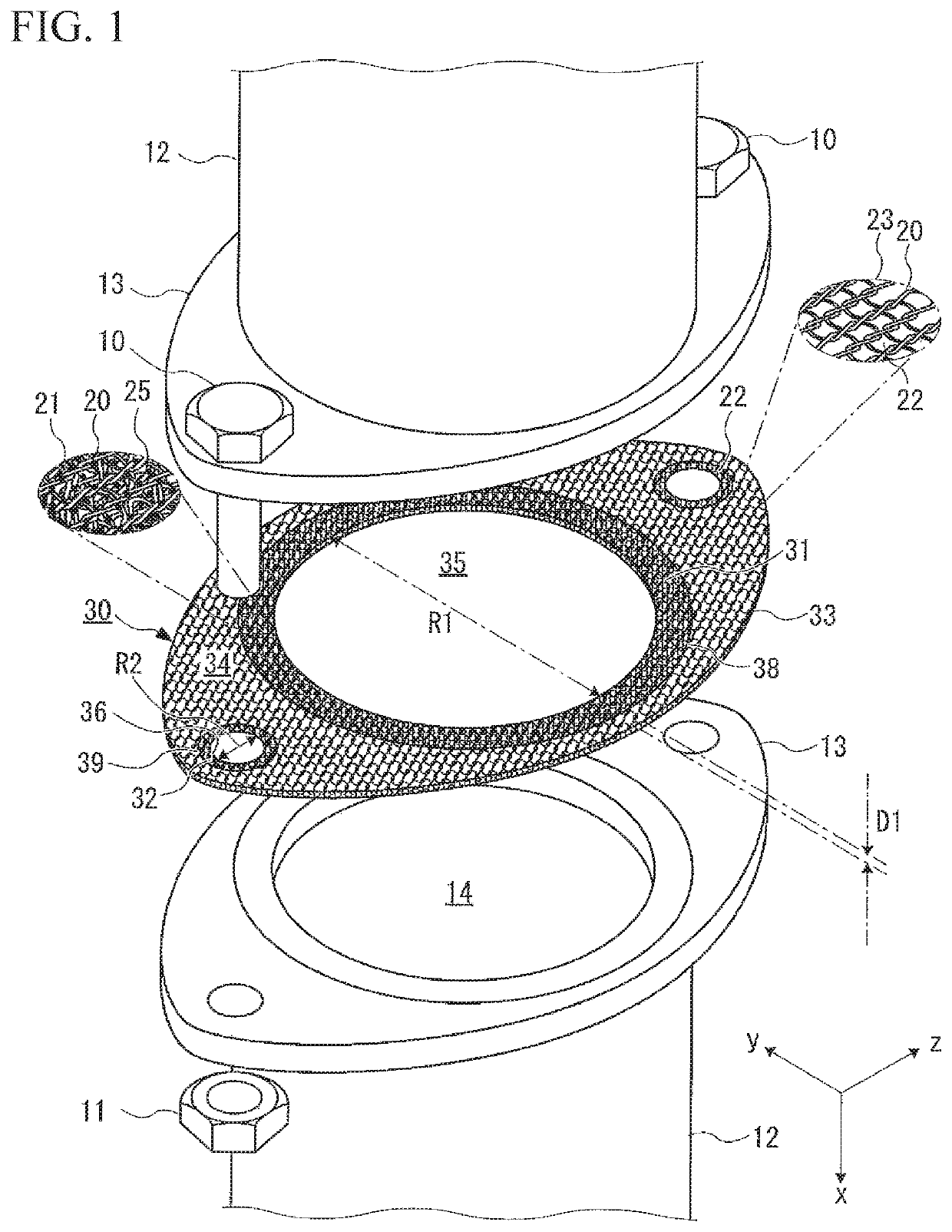
[0014]As illustrated in FIG. 1, a gasket 30 of a first embodiment is a gasket for a flange to be fastened by bolts 10 and nuts 11 while being sandwiched between flanges 13 of pipes 12.

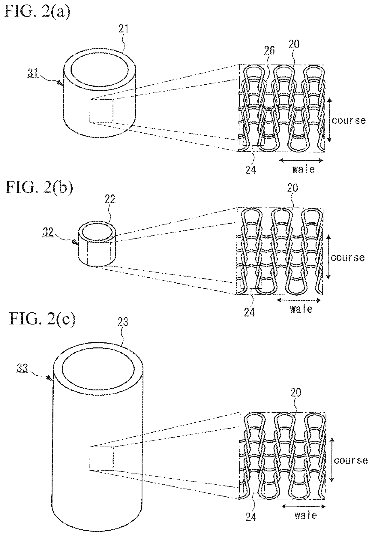
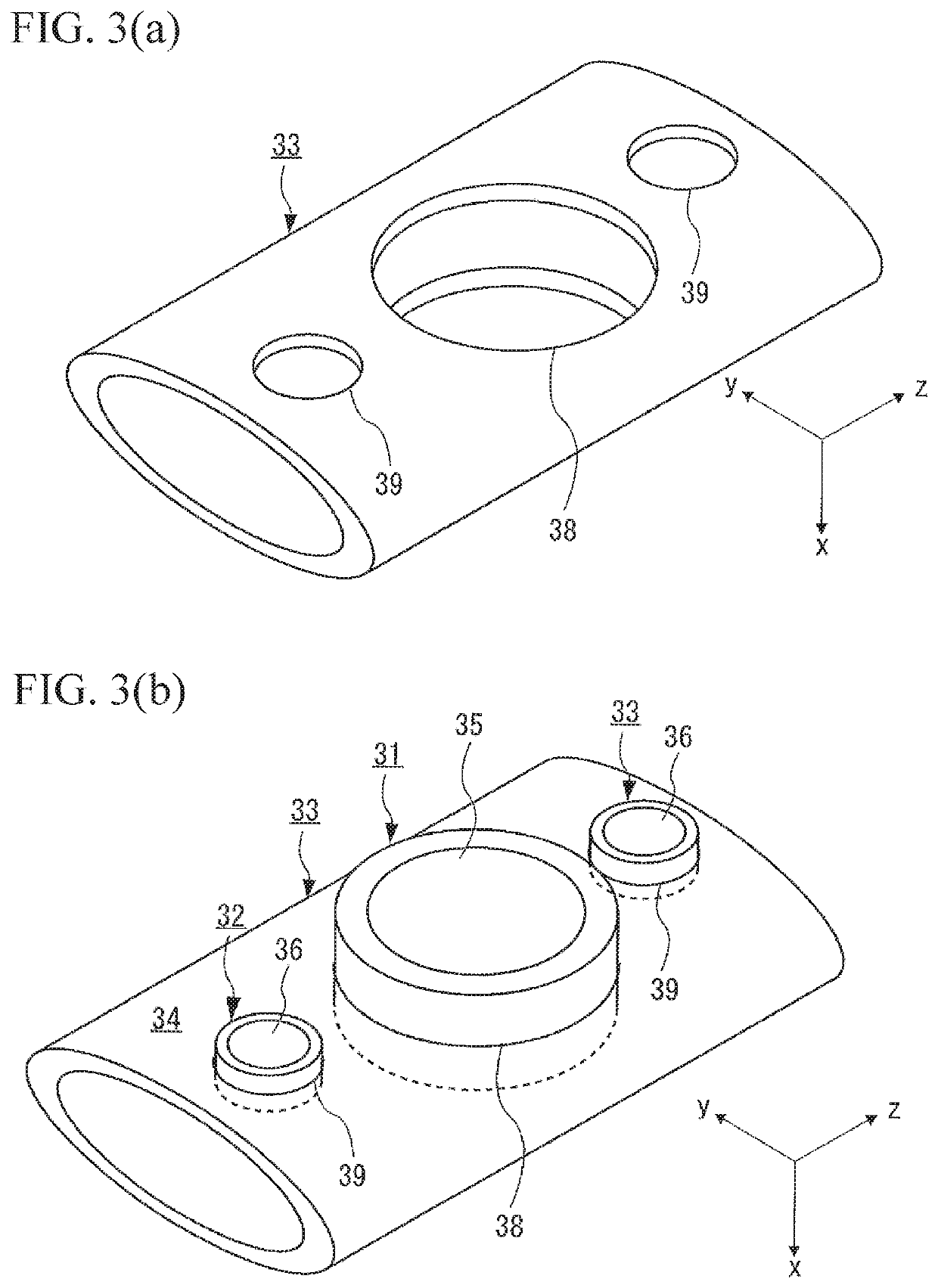
[0015]The gasket 30 is formed by metal wire woven fabrics 21 to 23 obtained by weaving a metal wire 20 and includes a first annular portion 31 which is formed by the metal wire woven fabric 21, a second annular portion 32 which is formed by the metal wire woven fabric 22, and a main body portion 33 which is formed by the metal wire woven fabric 23. The gasket 30 includes a plate surface 34 in which the metal wires 20 of the metal wire woven fabrics 21 to 23 forming each of the first annular portion 31, the second annular portion 32, and the main body portion 33 are entangled with one another to be joined together and which is formed at both ends in the x direction to extend in the plane yz and has a single plate shape of which a plate thickness D1 in the x direction is 0.4 mm to 2.0 mm.

[0016]The metal ...

second embodiment

[0048]As illustrated in FIG. 4, in the gasket 30 of a second embodiment, the first annular portion 31, the second annular portion 32, and the main body portion 33 have different compressive stresses in the x direction while the gasket 30 is sandwiched between the flanges 13 of the pipes 12 and is fastened by the bolts 10 and the nuts 11.

[0049]The compressive stresses for the first annular portion 31, the second annular portion 32, and the main body portion 33 are generated when the tightening force (fastening force) generated by the bolts 10 and the nuts 11 becomes equal to or larger than the degree that the plate surface 34 becomes familiar to the seat surface of the flange 13 (the degree that both plate surfaces 34 contact the seat surface of the flange 13 without gaps).

[0050]Specifically, in the embodiment, the first annular portion 31, the second annular portion 32, and the main body portion 33 have different volume densities of the metal wires 20 in the metal wire woven fabrics...


PUM

PropertyMeasurementUnit
thickness D1aaaaaaaaaa
diameteraaaaaaaaaa
temperatureaaaaaaaaaa

Abstract

An object of the present invention is to provide a gasket capable of maintaining a surface pressure for a long period of time while securing sealing performance and improving durability and a manufacturing method thereof. A gasket includes a first annular portion which is formed by a metal wire woven fabric and has a seal target hole and a main body portion which is formed by a metal wire woven fabric and is in contact with an outer peripheral edge of the first annular portion, in which a metal wire of the metal wire woven fabric and a metal wire of the metal wire woven fabric are entangled so that the first annular portion and the main body portion are joined to each other and a gap between the metal wires forming the first annular portion is sealed by a resin.

Description

RELATED APPLICATIONS[0001]The present applications claim priority from Japanese Application No. 2017-082494, filed Apr. 19, 2017, the disclosure of which is hereby incorporated by reference herein in its entirety.BACKGROUND OF THE INVENTIONTechnical Field[0002]The present invention relates to a gasket and a gasket manufacturing method, and more particularly, to a gasket having improved durability and a manufacturing method thereof.Related Art[0003]As a gasket which requires surface pressure adjustment, such as a gasket sandwiched between a cylinder head and a cylinder block and a gasket sandwiched between flanges of exhaust pipes, a gasket obtained by laminating a plurality of metal plates, has been used (for example, see JP 2016-142242 A). In such a gasket, a bead or fold is formed in the metal plate to adjust a surface pressure.SUMMARY OF THE INVENTION[0004]However, when the gasket is fastened for a long period of time, the formed bead or fold is stretched due to stress or thermal...

Claims


Application Information

Patent Timeline
Patent Type & Authority Patents(United States)
IPC IPC(8): F16J15/12F16J15/10F02F11/00
CPCF16J15/126F16J15/123F16J15/102F16J15/104F16J15/122F02F11/002D03D2700/0137D10B2505/06F16J15/022F01N13/1827
Inventor KINOSHITA, YUICHI
Owner ISHIKAWA GASKET CO LTD
Why Eureka
Try Eureka