CDMA-based 3D imaging method for focal plane array LIDAR

a 3d imaging and lidar technology, applied in the field of 3d imaging methods for focal plane array lidar, can solve the problems of significantly reducing range accuracy, low detection noise, and increasing size and weight, and achieve accurate range demodulation of pixels and reduce information redundancy of 22n target pixels.

Active Publication Date: 2020-03-17
NANJING UNIV OF AERONAUTICS & ASTRONAUTICS
View PDF2 Cites 4 Cited by
  • Summary
  • Abstract
  • Description
  • Claims
  • Application Information

AI Technical Summary

Benefits of technology

[0030](1) The presented focal plane array LIDAR uses a plane array detection mode that provides scannerless, large-FOV, real-time remote sensing, thereby achieving a “staring” 3D imaging.
[0031](2) The CDMA technique is applied to the focal plane array LIDAR. On the one hand, it reduces the information redundancy of the 22N target pixels by labeling them with orthogonal codes and achieves an accurate range demodulation of the pixels. On the other hand, the multiplexing technique achieves high-resolution 3D imaging with small-scale detectors, i.e., M×22N subpixels with only an M-element detector array.
[0032](3) Considering (1) and (2), the 256×64 (i.e., M=214) APD array developed by the Lincoln Laboratory can achieve 268-million pixels per frame for 3D imaging when combined with a 128×128 (i.e., 2N=214) focal plane array encoder.

Problems solved by technology

A scanning imaging LIDAR is operated by scanning the object point-by-point with a mechanical scanning device, which not only increases the size and the weight but also results in bias.
However, current algorithms may result in significantly lower range accuracy.
Third, the highly sensitive and precise APD array results in low detection noise, long detection range, high number of imaging frames, and high precision.
However, the conventional measurement method whereby imaging resolution relies on the array scale limits the further development of LIDAR systems.
Simply upgrading the APD array scale to improve the imaging resolution not only increases the difficulty of hardware design and the cost but also hampers the system's miniaturization and integration.

Method used


Image

  • CDMA-based 3D imaging method for focal plane array LIDAR
  • CDMA-based 3D imaging method for focal plane array LIDAR
  • CDMA-based 3D imaging method for focal plane array LIDAR

Examples


Embodiment Construction

[0041]A detailed description of the invention is provided as follows on the basis of the accompanying drawings.

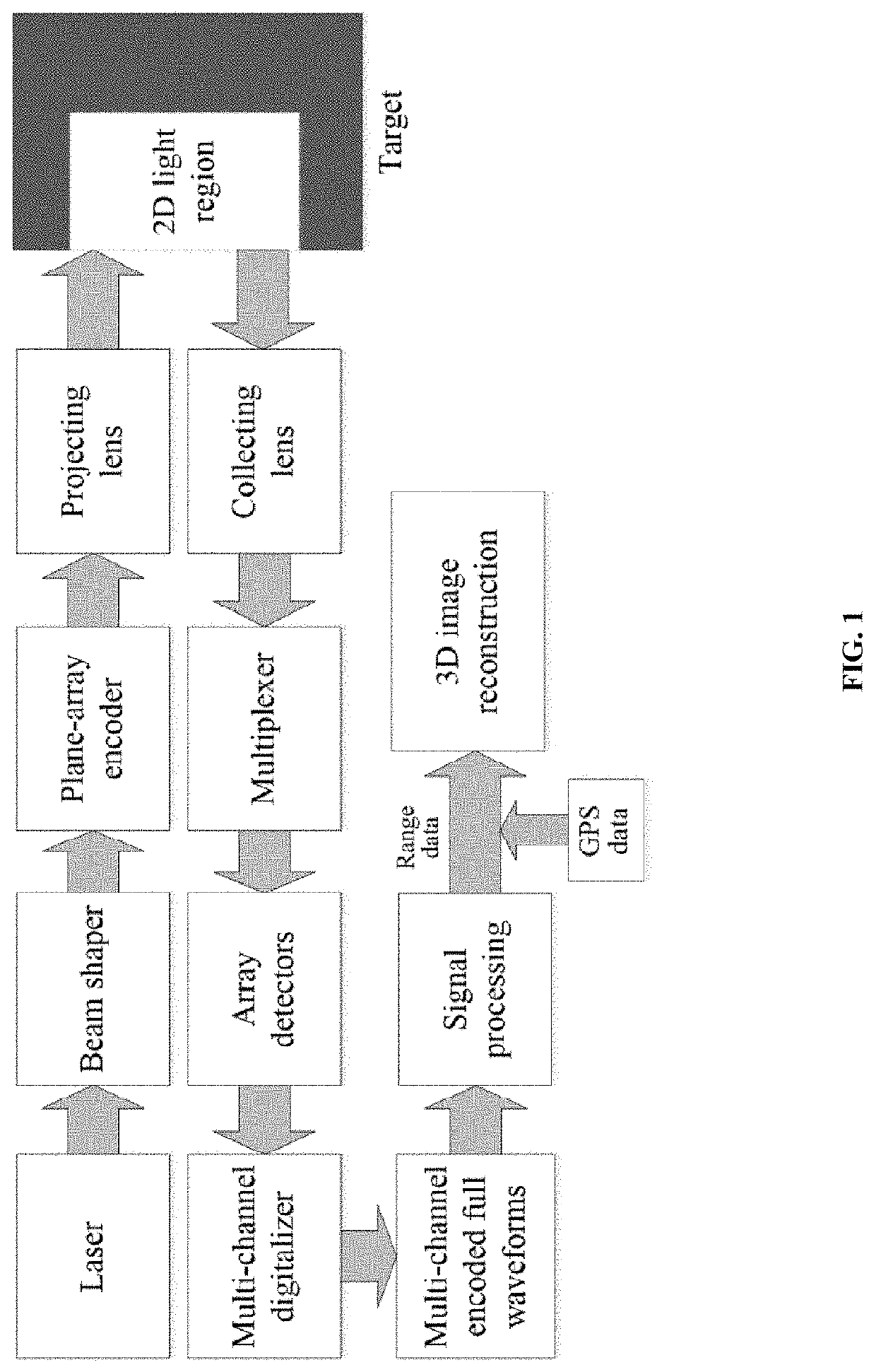
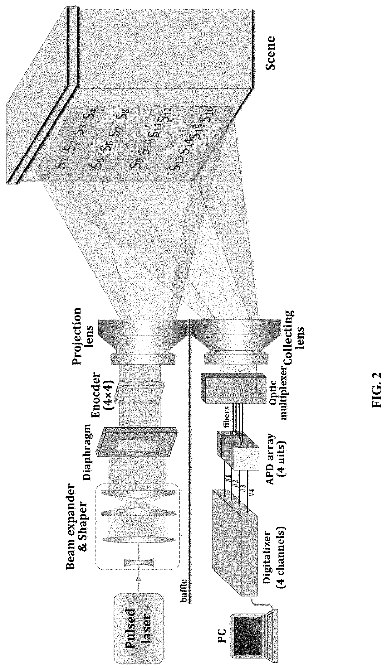
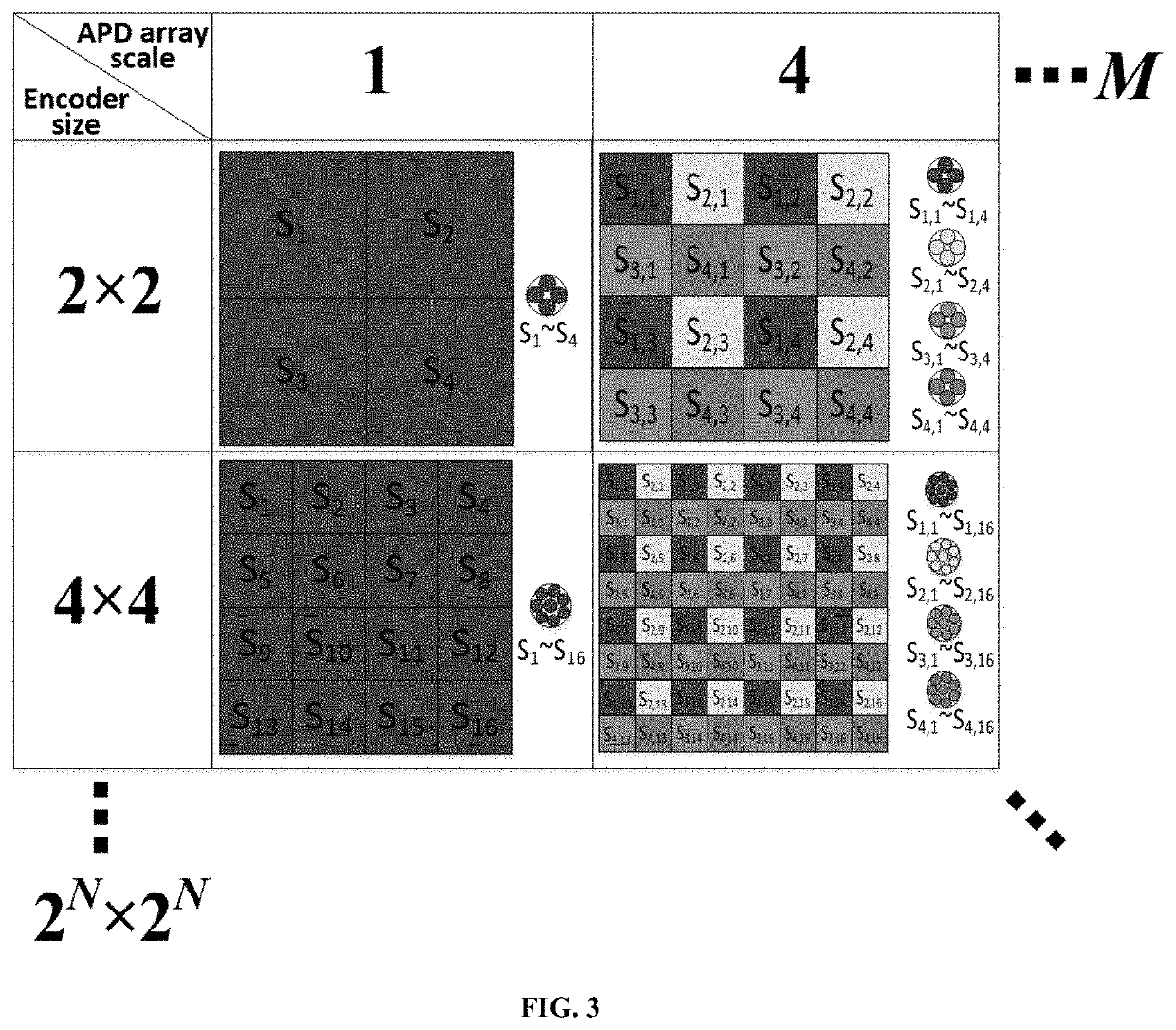
[0042]As shown in FIG. 1, the presented CDMA-based 3D imaging method for the focal plane array LIDAR consists of three components involving emission, receiving, and signal processing. The emission process consists of laser shaping and encoding, while the receiving process executes the collection and multiplexing. The signal processing involves signal enhancement, signal demodulation, parameter extraction, and 3D image reconstruction. Compared with a conventional LIDAR imaging method, three modules including laser shaping, encoding, multiplexing, and signal demodulation are added to achieve a large FOV, low data redundancy, a high coefficient of detector utilization, and high range precision. The detailed operation is as follows. The laser is shaped into a flat-top beam and further encoded by a focal plane array encoder. For example, if the size of the encoder is 2N×2N, the ...


PUM


Abstract

A focal plane array light detection and ranging 3D imaging method based on a code division multiple access technique is provided. A narrow laser pulse is shaped into a flat-top beam. The shaped beam is space-time encoded by a focal plane array-based optical encoder. The encoded beam is projected onto the target. The echo signals are obtained by a collecting lens. According to the encoding rule, the signals are grouped and multiplexed into several channels; subsequently, the multi-channel multiplexed signals are captured by a focal plane array detector and converted by a multi-channel digitizer. The multi-channel encoded full waveform signals are acquired from the digitizer by a PC terminal. The encoded full waveforms can be demodulated into the flight ranges for all subpixels via signal processing. By orthogonal range correction and pixel splicing and integrating the geographical data of all pixels, the 3D image reconstruction of the target can be accomplished.

Description

CROSS-REFERENCE TO RELATED APPLICATION[0001]This application claims the priority benefit of China application serial no. 201710150139.8, filed on Mar. 14, 2017. The entirety of the above-mentioned patent application is hereby incorporated by reference herein and made a part of this specification.BACKGROUND OF THE INVENTIONField of the Invention[0002]The present invention relates to a 3D imaging method for a focal plane array LIDAR and specifically to a code division multiple access (CDMA)-based 3D imaging method for a focal plane array LIDAR, belonging to the field of laser 3D imaging technologies or laser remote sensing technologies.Description of Related Art[0003]LIDAR, short for light detection and ranging, is an active photoelectric imaging technology. It is widely applied not only in the military field for laser guidance, battlefield reconnaissance, aircraft collision prevention, landmine detection, etc. but also in the scientific domain for urban mapping, forest ecological mon...

Claims


Application Information

Patent Timeline
Patent Type & Authority Patents(United States)
IPC IPC(8): G01S17/89G01S7/4863G01S7/481G01S7/486G01S7/487G01S7/4865G01S17/894
CPCG01S7/4865G01S17/89G01S7/487G01S7/4863G01S7/4818G01S7/4811G01S17/894
Inventor XU, FAN
Owner NANJING UNIV OF AERONAUTICS & ASTRONAUTICS
Why Eureka
Try Eureka