Plug-and-play ripple pacifier for DC voltage links in power electronics systems and DC power grids

a ripple pacifier and voltage link technology, applied in hot plugging-unplugging power/load, power conversion systems, pulse duration/width modulation, etc., can solve the problems of reduced utilization and heating, increased low-frequency voltage ripple at the dc port, and reduced effective capacitance, so as to achieve simple hardware and control of the rp

Active Publication Date: 2020-03-17
THE UNIVERSITY OF HONG KONG
View PDF13 Cites 5 Cited by
  • Summary
  • Abstract
  • Description
  • Claims
  • Application Information

AI Technical Summary

Benefits of technology

[0017]As an active power filter or ripple pacifier, another advantage of the invention is that the practical impedance used in the programmable device can be much smaller than the emulated impedance, making it possible to use non-electrolytic capacitors. Applications of the proposed plug-and-play device include at least, but not limited to, voltage ripple pacifiers and active power filters.
[0018]Additionally, if the RP is made sufficiently compact, e.g. similar to the size of an E-Cap, it can be used as a discrete component in the form of an Active Electronic Capacitor. Thus, other than being applied to DC-link systems, the RP can be used to directly replace short-lifetime E-Caps in power supplies and equipment. In this respect, the RP can be modularized and arranged in parallel-series configurations, which can be beneficial to high power or distributed power system applications, where “hot swapping” of faulty units can be easily performed without interrupting the normal functioning of the system. Both the hardware and the control of the RP are simple and of low cost.
[0019]It is important to note that the RP can be further enhanced to include the additional feature of alleviating transient disturbance on the DC-link. This is useful for applications involving fast dynamic power changes of source or load.
[0020]The device of the present invention has the following advantages:—
[0021]A. Compared to most of the existing prior art systems, it requires no additional sensors installed into the existing DC system for measuring the system status. Only the DC-link voltage / current information is required.
[0022]B. The use of the proposed method will only regulate the ripple (high frequency) content in the DC-link voltage and will not affect the averaged DC value of the DC-link voltage.

Problems solved by technology

This leads to a decrease in the effective capacitance and therefore an increase in the low-frequency voltage ripple at the DC port.
For instance, with the RP absorbing the ripple power, there is minimal flow of low-frequency current in the E-Caps, which means reduced utilization and heating, and consequently, the prolonging of their lifespan.

Method used


Image

  • Plug-and-play ripple pacifier for DC voltage links in power electronics systems and DC power grids
  • Plug-and-play ripple pacifier for DC voltage links in power electronics systems and DC power grids
  • Plug-and-play ripple pacifier for DC voltage links in power electronics systems and DC power grids

Examples


Embodiment Construction

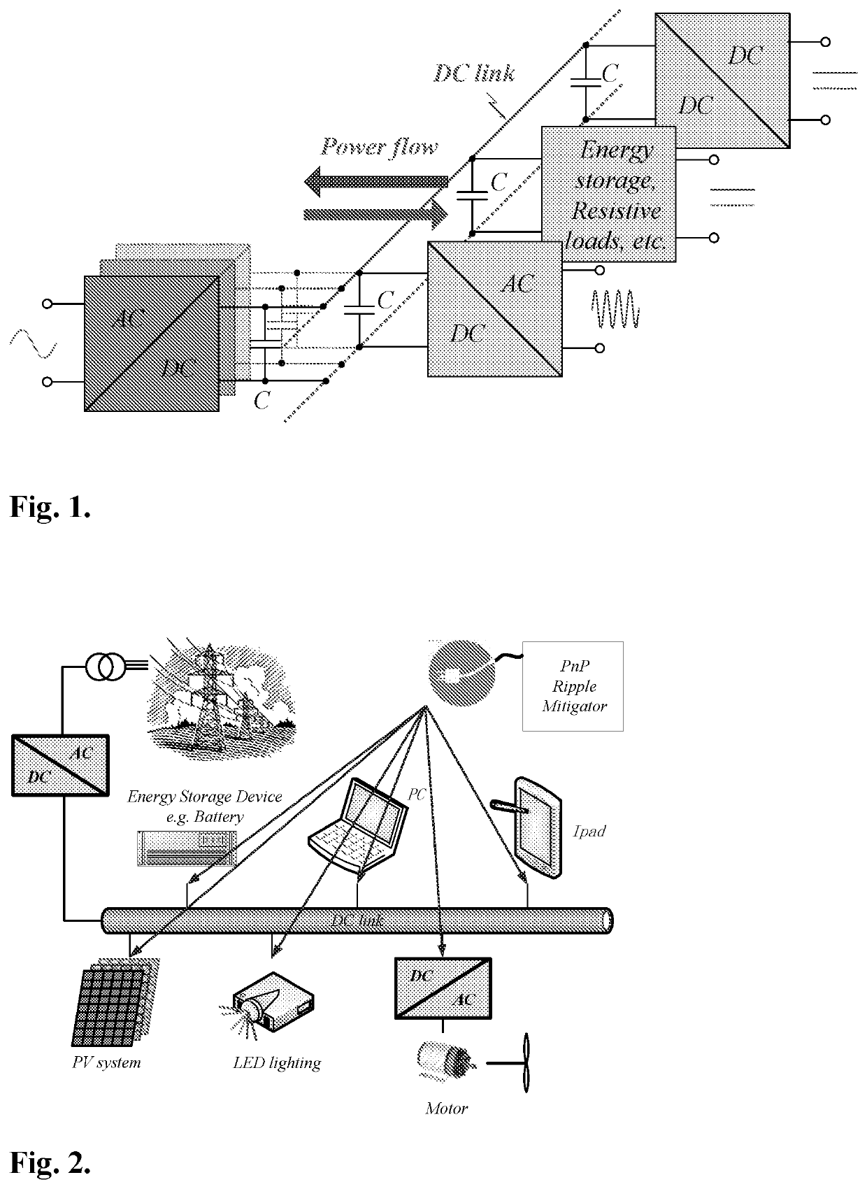
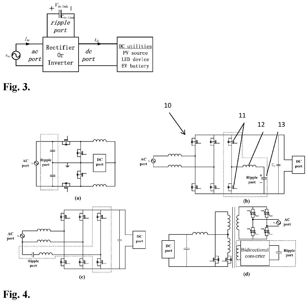
[0052]As shown in FIG. 3, at the ripple port there is an energy storage device that absorbs only the DC voltage ripple. As a result the E-Cap next to the ripple port becomes optional. Besides, the current invention is connected in parallel with the DC utilities at the DC-link interface, thus it can be plugged into the system without any modification (plug-and-play).

[0053]Therefore, for AC / DC systems, the current invention can eliminate the use of E-Caps to improve the overall system stability. For existing system with pre-installed E-Caps, it can also serve as a protection apparatus to slow down the degradation of the E-Caps. For integrated systems, the current invention can replace short-lifetime E-Caps directly to improve the lifetime of the application.

[0054]FIG. 4 shows various illustrative examples of circuits related to each kind of ripple port configurations. In each figure the circuit for performing the ripple pacifying function is shown in dotted lines. The input side repre...


PUM


Abstract

In many power electronics systems, there is an intermediate DC-link stage for facilitating the power processing of different sources to their loads. A device called a plug-and-play ripple pacifier (RP) directly plugged into the DC-link, and actively removes undesired DC-link ripple, thereby eliminating the reliance on electrolytes capacitors for stabilizing the system and remove ripple. Importantly, the use of this device is non-invasive to the operation of its host systems, and requires no modification of existing hardware. It is suitable for the protection of DC utilities / systems and can also be used as a direct replacement of ripple-canceling E-Caps in power converters device.

Description

CROSS-REFERENCE TO RELATED PATENT APPLICATIONS[0001]This application is a U.S. National Phase Application under 35 U.S.C. § 371 of International Patent Application No. PCT / CN2015 / 092649, filed Oct. 23, 2015, which is incorporated by reference in its entirety. The International Application was published on Apr. 27, 2017 as International Publication No. WO 2017 / 066985 A1.FIELD OF THE INVENTION[0002]The current invention relates to achieving ripple mitigation and stabilization of DC utilities and systems using a device that is fully independent of the operation of existing power electronic equipment and electrical appliances connected to DC-link infrastructure.BACKGROUND OF THE INVENTION[0003]In recent years, with emerging distributed renewable power generation, such as photovoltaic power generation, there has been a renewed interest in dc power grids. It is envisaged that a mixture of traditional AC power grids and emerging dc power grids will become a new form of power gird for the f...

Claims


Application Information

Patent Timeline
Patent Type & Authority Patents(United States)
IPC IPC(8): H04M1/15H02M1/15H02M7/217H02J1/02H03K7/08H02M7/48
CPCH02M7/4826H02J1/02H03K7/08H02M7/217H02M1/15H02J1/001
Inventor LI, SINANLEE, TING LEUNG ALBERTTAN, SIEW CHONGHUI, SHU YUEN RON
Owner THE UNIVERSITY OF HONG KONG
Why Eureka
Try Eureka