

Radio communication system
a radio communication system and radio communication technology, applied in the field of radio communication systems, can solve the problems of difficult to apply the techniques of mobile communication and indoor radio communication to the radio communication system used in a factory or the like, and the processing of existing mobile communication and indoor radio communication techniques is generally complicated, and it is difficult to control the antenna beam
- Summary
- Abstract
- Description
- Claims
- Application Information
AI Technical Summary
Benefits of technology
Problems solved by technology
Method used
Image

Examples
first embodiment
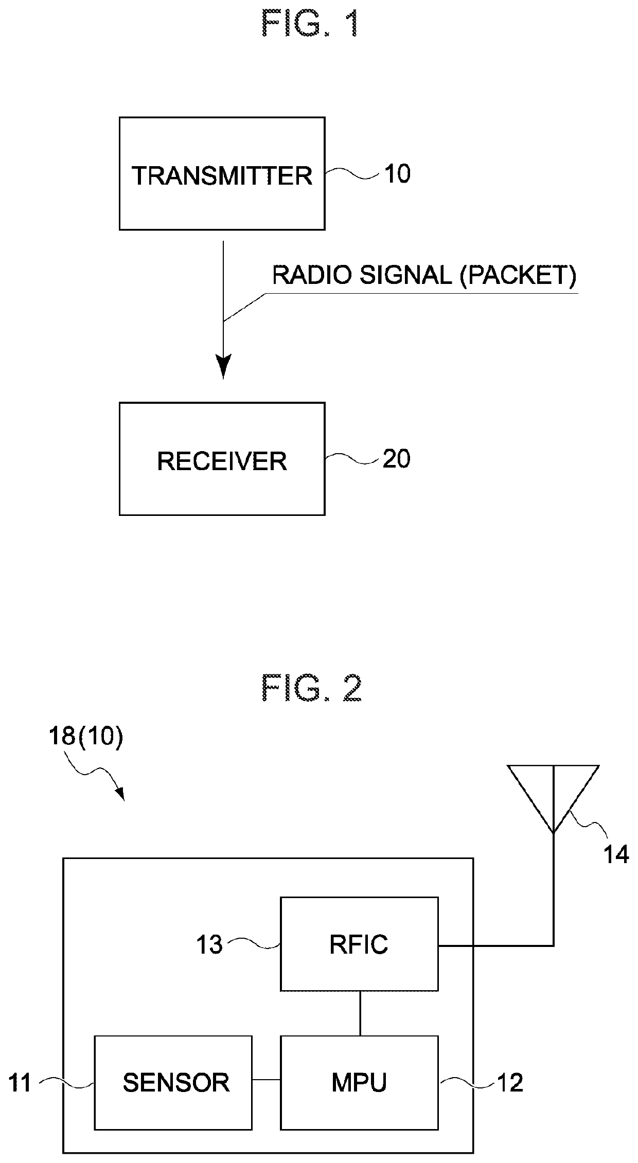
[0063]FIG. 1 illustrates a configuration of a radio communication system according to the first embodiment of the present invention.
[0064]As illustrated, the radio communication system according to the present embodiment is a system including one transmitter 10 and one receiver 20.
[0065]The transmitter 10 serving as a component of the radio communication system according to the present embodiment is a device that periodically transmits a radio signal (hereinafter also referred to as a packet) including information to be transmitted to the receiver 20.
[0066]The transmitter 10 may be a device having a fixed transmission cycle of a packet, or may be a device capable of changing (specifying) the transmission cycle of a packet. Alternatively, the transmitter 10 may be a device having a fixed transmission timing (transmission start timing) of a packet, or may be a device capable of changing the transmission timing of a packet. Furthermore, the hardware configuration of the transmitter 10 ...
second embodiment
[0096]Hereinafter, a radio communication system according to a second embodiment of the present invention will be described focusing on differences from the radio communication system according to the first embodiment. In the following description of each embodiment, the radio communication system according to the n-th (n=1 to 3) embodiment is referred to as an n-th radio communication system.
[0097]FIG. 9 illustrates an example of the configuration of a second radio communication system (a radiocommunication system according to the second embodiment). As illustrated, the second radio communication system includes a plurality of communication systems (four communication systems A to D in the figure) each including one transmitter 30 and one receiver 20.
[0098]The receiver 20 (hereinafter, also referred to as a second receiver 20) serving as a component of the second radio communication system is a device obtained by modifying the receiver 20 of the first radio communication system so ...
third embodiment
[0114]Hereinafter, a radio communication system according to a third embodiment of the present invention will be described focusing on differences from the radio communication system according to the second embodiment.
[0115]FIG. 13 illustrates an example of the configuration of a third radio communication system (a radio communication system according to the third embodiment). As illustrated, the third radio communication system includes a plurality of communication systems each including a plurality of transmitters 35 and one receiver 20.
[0116]The receiver 20 (hereinafter, also referred to as a third receiver 20) serving as a component of the third radio communication system is a device obtained by modifying the receiver 20 of the second radio communication system so that the MPU 23 performs processes (details of which will be described later) different from the processes described above.
[0117]The transmitter 35 serving as a component of the third radio communication system is a de...
PUM
 Abstract
Description
Claims
Application Information