Monocular stereoscopic camera

a stereoscopic camera and monocular technology, applied in the field of monocular stereoscopic cameras, can solve the problems of inability to acquire stereoscopic images of high quality, inconvenient control of the mechanical position of the camera, and difficulty in capturing stereoscopic images, and achieves easy and rapid control. high quality

Active Publication Date: 2020-03-24
YEON SYST CO LTD
View PDF53 Cites 0 Cited by
  • Summary
  • Abstract
  • Description
  • Claims
  • Application Information

AI Technical Summary

Benefits of technology

[0016]A monocular stereoscopic camera according to the present invention may simply and easily (1) perform a control to make images captured by first and second cameras of the camera be identical to each other, (2) change an optical axis, (3) adjust a convergence angle, and (4) correct position errors of a third imaging lens assembly, a half mirror, and the camera, even without a manipulation of a position of the camera itself and a rotation of the camera itself.
[0017]Thus, a subject moving from moment to moment at a photographing site is easily and rapidly controlled in accordance with a situation, a stereoscopic image having high quality, on which a 3-dimensional effect is represented well, can be acquired.

Problems solved by technology

It is practically difficult to capture a stereoscopic image while the left-eye camera and the right-eye camera finely moves forwards / rearwards, and it is very inconvenient to perform a control to change mechanical positions of the cameras.
When optical axes are not aligned with each other, a stereoscopic image having high quality cannot be acquired.
However, as described above, Korean Patent No. 1214855 has a problem in that because a structure of the adjustment modules is very complex, applicability to a photographing site in which a subject moving from moment to moment is photographed deteriorates, and costs consumed for commercialization is high.
Because there is an error when a lens is manufactured, it is difficult to manufacture lenses having the same physical characteristics.
It is very difficult to capture a precise stereoscopic image using two lenses having different physical characteristics.

Method used


Image

  • Monocular stereoscopic camera
  • Monocular stereoscopic camera
  • Monocular stereoscopic camera

Examples


first embodiment

[0035](1) First Embodiment

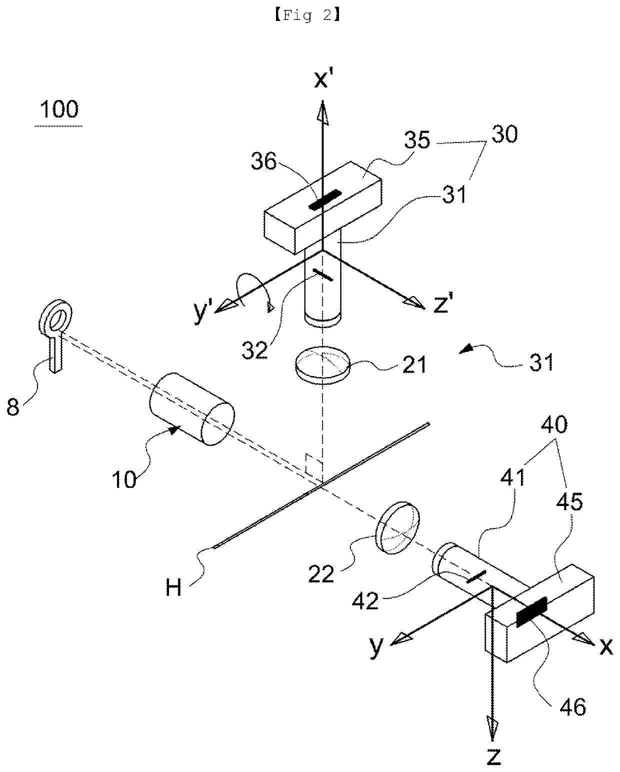
[0036]FIG. 2 is a schematic illustrating a monocular stereoscopic camera according to a first embodiment of the present invention; Referring to FIG. 2, a monocular stereoscopic camera 100 according to the present invention includes a first imaging lens assembly 10, a half mirror H, second imaging lens assemblies 21 and 22, third imaging lens assemblies 31 and 41, a first camera 30 and a second camera 40.

[0037]The first imaging lens assembly 10 collects a light beam input from a subject 8. The light beam passing through the first imaging lens 10 is moved to the half mirror H. The half mirror H reflects a portion of the light beam and penetrates the other portion of the light beam. The light beam reflected by the half mirror H passes through the second imaging lens assembly 21, and is then imaged on the third imaging lens assembly 31, and the light beam passing through the half mirror H passes through the second imaging lens assembly 22 and is then imaged on ...

second embodiment

[0064](2) Second Embodiment

[0065]FIG. 6 is a schematic view illustrating a monocular stereoscopic camera according to a second embodiment of the present invention; Hereinafter, in the stereoscopic camera 200 according to a second embodiment of the present invention, because the same configuration as that of the stereoscopic camera 100 according to the first embodiment uses the same name, all other configurations except for an arrangement relationship should be interpreted in the same sense.

[0066]Referring to FIG. 6, the stereoscopic camera 200 according to the second embodiment is a horizontal rig in which optical axes connecting the half mirror H and the third imaging lens assemblies 31 and 41 are parallel or almost parallel to each other. In detail, the optical axis connecting the second imaging lens assembly 21 and the third imaging lens assembly 31 and the optical axis connecting the second imaging lens assembly 22 and the third imaging lens assembly 41 are arranged to be parall...

third embodiment

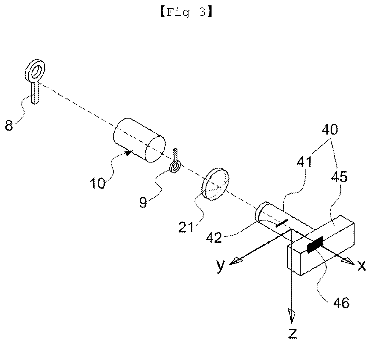
[0070](3) Third Embodiment

[0071]FIG. 7 is a schematic view illustrating a stereoscopic camera according to a third embodiment of the present invention; In the stereoscopic camera 300 according to a third embodiment of the present invention, because the same configuration as that of the stereoscopic camera 100 according to the first embodiment uses the same name, all other configurations except for an arrangement relationship should be interpreted in the same sense.

[0072]Referring to FIG. 7, in the stereoscopic camera 300, the second imaging lens assembly 20 is arranged between the first imaging lens assembly 10 and the half mirror H, and the second imaging lens assemblies 21 and 22 are arranged between the half mirror H and the third imaging lens assemblies 31 and 41.

[0073]The second imaging lens assemblies 20, 21, and 22 are moved, panned, and tilted along the optical axes in the same scheme as that described in the stereoscopic camera 100 according to the first embodiment.

[0074]Th...


PUM


Abstract

The present invention relates to a monocular stereoscopic camera for capturing a stereoscopic image of an object, and the monocular stereoscopic camera according to the present invention has: a first imaging lens assembly; a half mirror for reflecting a portion of light rays which have passed through the first imaging lens assembly while allowing the remaining light rays to pass through; a first camera including a third imaging lens assembly for imaging the light rays which have been reflected by the half mirror; a second camera including a third imaging lens assembly for imaging the light rays which have passed through the half mirror; and a second imaging lens assembly arranged on an optical axis between the first imaging lens assembly and the half mirror or on an optical axis between the half mirror and the third imaging lens assembly.

Description

CROSS-REFERENCE TO RELATED APPLICATIONS[0001]This application is a 371 of PCT / KR2016 / 015239, filed on Dec. 23, 2016, which claims the benefit of Korean Patent Application No. 10-2015-0186872 filed Dec. 24, 2015 the contents of each of which are incorporated herein by reference.TECHNICAL FIELD[0002]The present invention relates to a monocular stereoscopic camera for capturing a stereoscopic image of a subject, and more particularly, to a monocular stereoscopic camera which may identically control an image rapidly and precisely captured by a camera at a photographing site, may change an optical axis, may adjust a convergence angle, and may correct a position error of the camera.BACKGROUND ART[0003]A stereoscopic camera is a camera capable of simultaneously acquiring a left-eye image and a right-eye image of a subject using two cameras, and the general stereoscopic camera includes a left-eye camera configured to acquire a left-eye image of a subject and a right-eye camera configured to...

Claims


Application Information

Patent Timeline
Patent Type & Authority Patents(United States)
IPC IPC(8): H04N13/204G03B35/10G02B27/14G03B35/08G02B27/10G02B7/02G02B7/04G02B7/10G02B13/00
CPCG02B13/0095G02B7/04G03B35/10G02B27/106G03B35/08G02B27/1066G02B7/02G02B7/10G02B27/144H04N13/204H04N13/236G02B7/022G02B13/009
Inventor PYO, DO-YEON
Owner YEON SYST CO LTD
Why Eureka
Try Eureka