Spring-forming control system and its control method for a spring forming machine

a control system and control method technology, applied in the field of spring forming machines, can solve the problems of low working efficiency, complex process, and inhumane approach to prior art interference design, and achieve the effects of reducing error rate, improving working efficiency, and easy and rapid operation control

Inactive Publication Date: 2010-03-09
TZYH RU SHYNG AUTOMATION
View PDF10 Cites 3 Cited by
  • Summary
  • Abstract
  • Description
  • Claims
  • Application Information

AI Technical Summary

Benefits of technology

[0007]The present invention has been accomplished under the circumstances in view. It is the main object of the present invention to provide a spring-forming control system and its control method for a spring forming machine, which provides graphical user interfaces (GUIs) for easy and rapid operation control. The human-factor engineering characteristic of the present invention greatly improves the working efficiency and reduces the error rate.

Problems solved by technology

This procedure is complicated.
Therefore, this prior art interference design is complicated and not with a humanized approach.
To a beginner, it is difficult to learn and operate a spring-forming control system without graphicalized software, resulting in low working efficiency.

Method used


Image

  • Spring-forming control system and its control method for a spring forming machine
  • Spring-forming control system and its control method for a spring forming machine
  • Spring-forming control system and its control method for a spring forming machine

Examples


Embodiment Construction

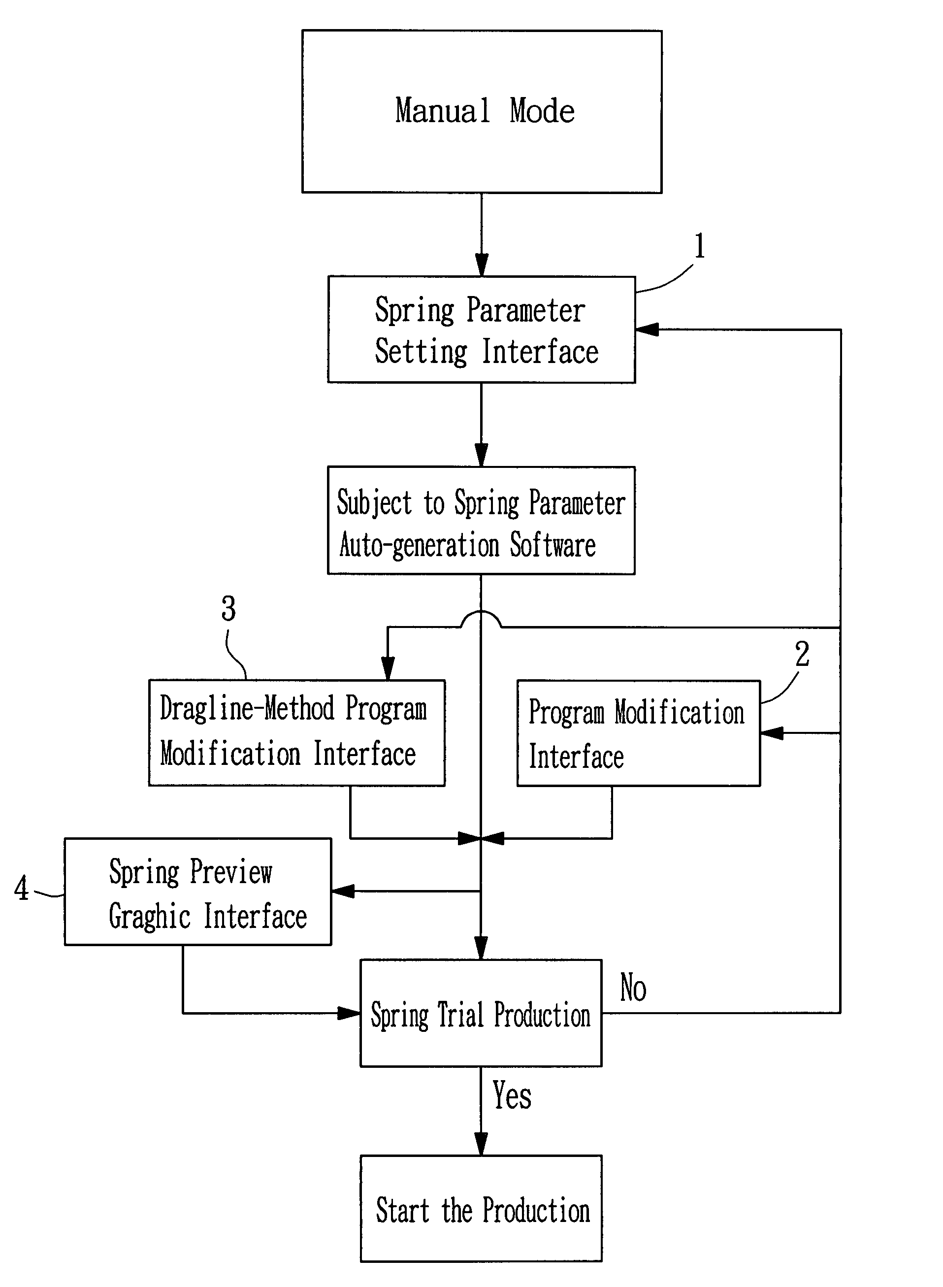
[0022]The invention provides a spring-forming control system for use in a spring forming machine to make springs subject to a predetermined spring-forming method. The host computer of the spring-forming control system shows all data on a display monitor (a) by a diagram interface of graphic interface (see FIG. 3). What is displayed on FIG. 3 is the main menu. The main menu shows simulation menus of Manual Mode (a1), Feed (a2), Cutter Setting (a3), Carbon Needle (a4), Upper / Lower Cylinder (a5), Material Rack (a6), Quantity Diagram (a7), and Machine Tools (a8). During operation enters setting through the Manual Mode (a1), and then enter parameter setting. The spring-forming control system allows selectively switching screens on the display monitor (a) of the host computer to show the Main Menu (see FIG. 3), or one of: the Spring Parameter Setting Interface (1) (see FIG. 5) the Program Modification Interface (2) (see FIG. 7). the Dragline- Method Program Modification Interface (3) (see...


PUM

PropertyMeasurementUnit
Diameteraaaaaaaaaa
processingaaaaaaaaaa
ODaaaaaaaaaa

Abstract

A spring-forming control system and its control method for a spring forming machine in which the spring-forming control system uses a host computer to provide graphical spring parameter setting, program modification, and dragline-method program modification graphical interfaces that are selectively switchable on a display monitor. After setting of spring processing parameters through the spring parameter setting interface, a trial production is done subject to a spring parameter auto-generation software built in the spring-forming control system, and then the production is started if the trial meets the requirements, or the spring processing parameters are modified through the spring parameter setting interface, program modification interface, or dragline-method program modification interface if the trial does not meet the requirements, and then a further trial production is performed till the shaped spring meets the requirements. A spring preview is available during running of the spring-forming control system. The graphic interface operation has the advantages of convenience, rapidness, and accuracy.

Description

BACKGROUND OF THE INVENTION[0001]1. Field of the Invention[0002]The present invention relates to a spring forming machine and more particularly, to a spring-forming control system and its control method for a spring forming machine, which provides graphic interfaces for easy and rapid operation control.[0003]2. Description of the Related Art[0004]Conventional spring forming systems commonly have a spring-forming control system 100 (as shown in FIG. 1) for setting spring processing parameters (such as size, and etc.) and controlling the spring forming processing operation of the machine. A spring-forming control system 100 for such a spring forming machine is known comprising a control panel 10 and a host (not shown). The control panel 10 has installed therein the display panel 20 and operation buttons 30 of the host.[0005]When the machine is started, it enters a manual mode for the setting of the standard specifications of the machine base (such as multiplication, count, wire rack, ...

Claims


Application Information

Patent Timeline
Patent Type & Authority Patents(United States)
IPC IPC(8): G06F19/00B21C47/00B21F3/02B21F3/10B23P13/00
CPCB21F35/00G05B19/4093Y10T29/49609G05B2219/36253Y10T29/49607G05B2219/36252Y02P90/02
Inventor CHANG, CHIH-FU
Owner TZYH RU SHYNG AUTOMATION
Why Eureka
Try Eureka