AC Link Bidirectional DC-DC Converter, Hybrid Power Supply System Using the Same and Hybrid Vehicle

a hybrid power supply system and converter technology, applied in the direction of batteries/cells, process and machine control, instruments, etc., can solve the problems of high electric power loss, deterioration of electric power conversion efficiency, and high power loss of the power supply system b>1, so as to reduce the size and weight of the transformer 53, reduce the current rating of the semiconductor switching element used in the inverter, and reduce the voltage rating of the semiconductor switching elemen

Inactive Publication Date: 2009-07-02
KOMATSU LTD
View PDF30 Cites 39 Cited by
  • Summary
  • Abstract
  • Description
  • Claims
  • Application Information

AI Technical Summary

Benefits of technology

[0071]When the first and eighth aspects of the invention are applied to the hybrid power supply system 3, as shown in FIG. 1, the voltage V0 of the main power supply 10 can be divided by the inverter 51 and the inverter 52, and hence the voltage rating of the semiconductor switching elements used in the inverters can be reduced. Further, when the first and eighth aspects of the invention are applied to the hybrid power supply system 3, electric current flowing through the capacitor 55 is divided between the inverter 51 and the inverter 52, and hence the current rating of the semiconductor switching elements used in the inverters can be reduced. The current reduction makes it possible to reduce the size and weight of the transformer 53, and to manufacture the transformer 53 at low cost.
[0072]Further, when the semiconductor switching elements of the inverter 51 and the inverter 52 are turned on, in most of the operating states, the turning on is conducted in a state where electric current flows through an antiparallel diode connected in antipolarity thereto. Therefore, the turning on can be performed easily under the condition of zero voltage switching (ZVS) and zero current switching (ZCS). As a result, the switching power loss can be reduced significantly without using any special means, and hence the transmission efficiency of the hybrid power supply system 3 can be improved.
[0073]According to the second and ninth aspects of the invention, as shown in FIG. 1, electric power transmission of the inverter 51 and the inverter 52 can be performed with the use of a leakage inductance, and the use of the leakage inductance makes it possible to perform bidirectional electric power control easily without adding any external inductance only by setting the leakage inductance inherently present in the transformer 53 to an appropriate value. It should be understood here that an external inductance may be added instead of relying only on the leakage inductance.
[0074]According to the third and tenth aspects of the invention, as shown in FIG. 1, the winding ratio of the transformer 53 can be determined according to a potential dividing ratio between the inverter 51 and the inverter 52. This makes it possible to change the voltage of the main power supply 10 and the range of voltage applicable to the capacitor 55 of the inverter 51 as required. Therefore, the capacitor 55 can be designed in consideration of the size and cost thereof.
[0075]According to the fourth and eleventh aspects of the invention, the voltage-current patterns as shown in FIGS. 2 and 3 can be controlled by means of phase difference control. Therefore, electric power transmission between the main power supply 10 and the capacitor 55 can be performed rapidly and easily by the AC link bidirectional DC-DC converter 64.
[0076]According to the fifth and twelfth aspects of the invention, the voltage-current pattern of the coil 57 and the voltage-current pattern of the coil 58 can be controlled rapidly and easily. Therefore, electric power transmission by the AC link bidirectional DC-DC converter can be performed rapidly and easily.

Problems solved by technology

However, the hybrid power supply system 1 has four problems as described below.
(3) High Electric Power Loss
Further, the semiconductor switch elements with a high voltage rating will suffer high conduction power loss and high switching power loss, causing deterioration of the electric power conversion efficiency, also due to the high voltage in the inverter circuit.
(4) Difficulty in Size Reduction and Cost Reduction
Cores with a large core cross-sectional area are expensive and difficult to reduce the size or weight.

Method used


Image

  • AC Link Bidirectional DC-DC Converter, Hybrid Power Supply System Using the Same and Hybrid Vehicle
  • AC Link Bidirectional DC-DC Converter, Hybrid Power Supply System Using the Same and Hybrid Vehicle
  • AC Link Bidirectional DC-DC Converter, Hybrid Power Supply System Using the Same and Hybrid Vehicle

Examples


embodiment 1

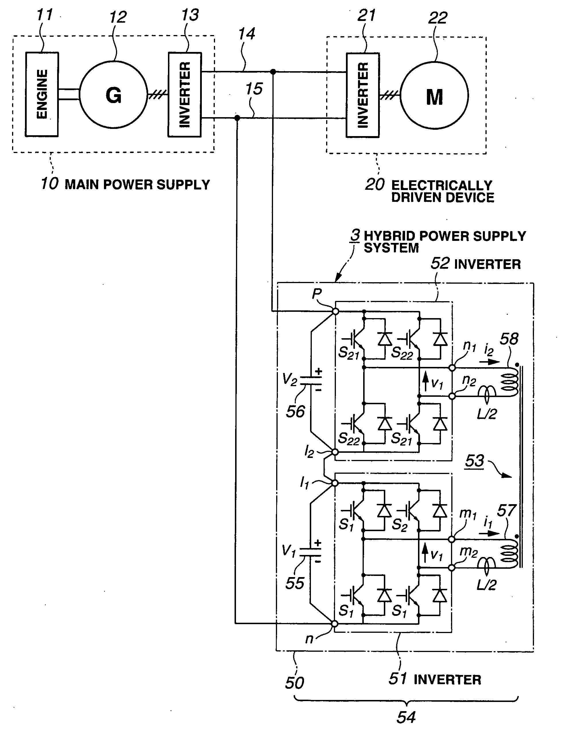
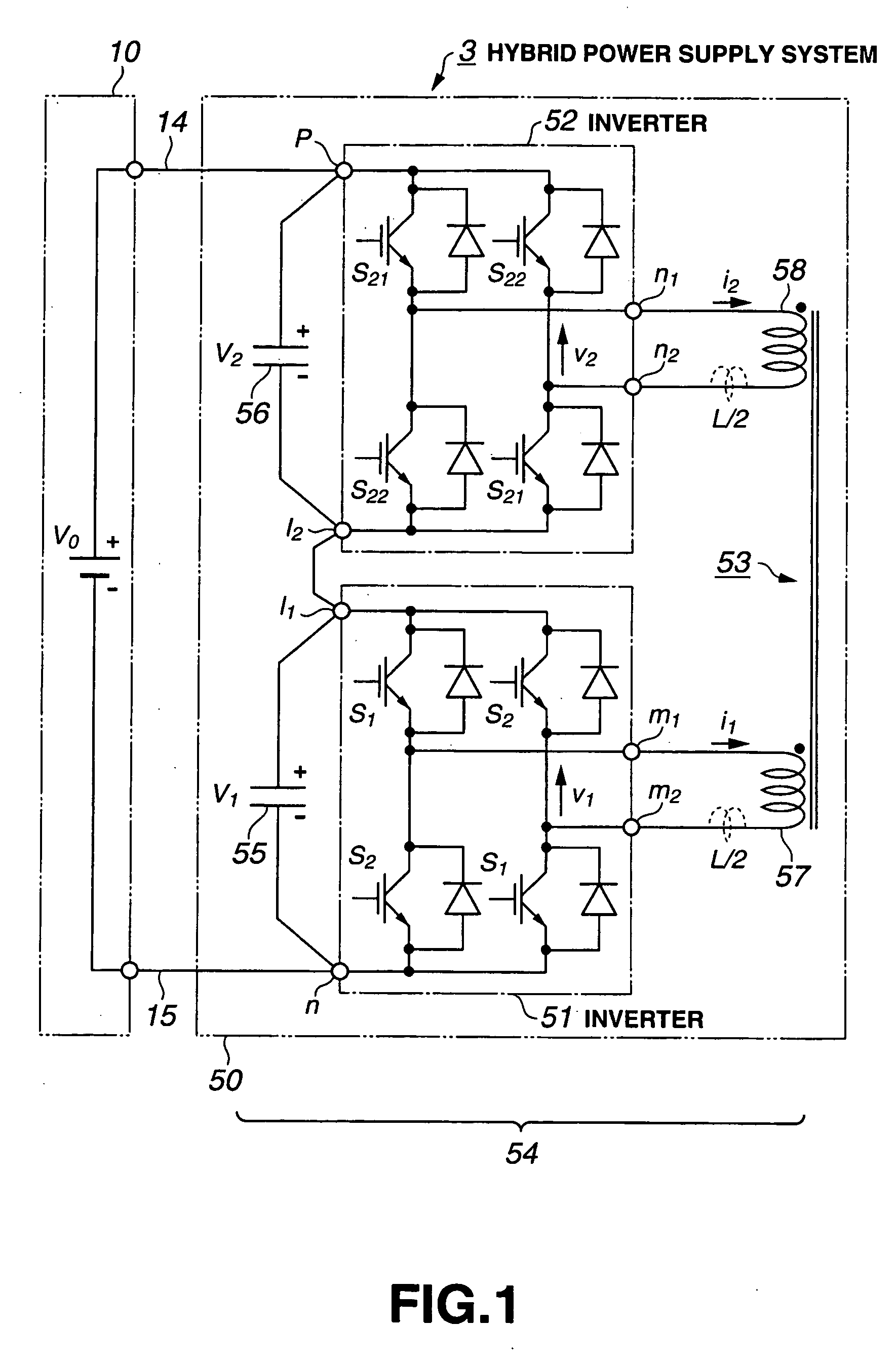
[0079]FIG. 1 is a diagram for explaining a hybrid power supply system employing an AC link bidirectional DC-DC converter according to the present invention.

[0080]As shown in FIG. 1, a hybrid power supply system 3 is composed of a main power supply 10 and an auxiliary power supply 50.

[0081]The main power supply 10 is connected to the auxiliary power supply 50 through a positive line 14 and a negative line 15.

[0082]The auxiliary power supply 50 is composed of an AC link bidirectional DC-DC converter 54 and a capacitor 55 (voltage V1) functioning as an energy accumulation device. The AC link bidirectional DC-DC converter 54 is composed of an inverter 51, an inverter 52, and a transformer 53. A condenser or the like may be used as an energy accumulation device in place of the capacitor 55.

[0083]The inverter 51 comprises four semiconductor switching elements S1, S1, S2, S2. The semiconductor switching elements are each formed by an IGBT and an antiparallel diode. The semiconductor switch...

embodiment 2

[0161]FIG. 8 is a diagram showing an AC link bidirectional DC-DC converter in which two inverters are each formed by a half-bridge circuit. In FIG. 8, components designated with the same reference symbols as in FIG. 1 have same or similar functions as those in FIG. 1. For the convenience of description, the following description will be made in terms of an embodiment in which the AC link bidirectional DC-DC converter is incorporated in a hybrid power supply system.

[0162]As shown in FIG. 8, an AC link bidirectional DC-DC converter 64 is formed by an inverter 51 comprising semiconductor switching elements S1, S2 and an inverter 52 comprising semiconductor switching elements S21, S22.

[0163]In the AC link bidirectional DC-DC converter 64, a positive DC terminal I1 of the inverter 51 is connected in series to a negative DC terminal I2 of the inverter 52 in additive polarity. The inverter 51 is connected in parallel to a serially-connected pair of capacitors 55a and 55b while polarities t...

embodiment 3

[0167]FIG. 9 is a diagram showing an AC link bidirectional DC-DC converter in which two inverters are formed by multiphase bridge connection. The following description will be made in terms of a three-phase bridge connection. Since the connection to the capacitor 55 and the main power supply 10 in this embodiment is basically same as that of Embodiment 1, the following description will be made only on different points from Embodiment 1.

[0168]In FIG. 9, the AC link bidirectional DC-DC converter 74 is formed by an inverter 51 comprising semiconductor switching elements S1, S2, S3, S4, S5, S6 and an inverter 52 comprising semiconductor switching elements S21, S22, S23, S24, S25, S26.

[0169]The inverter 51 has three pairs of semiconductor switching elements (S1, S2), (S3, S4), (S5, S6). Each pair of semiconductor switching elements is connected in series to each other and the three pairs are connected in parallel to each other. The inverter 52 has three pairs of semiconductor switching e...


PUM


Abstract

In an AC link type boosting device, DC terminals of two voltage inverters are connected each other in series in additive polarity and plural AC terminals of each of the voltage inverters are connected to a transformer. The two voltage type inverters are AC linked to each other via the transformer. An external voltage applied between the DC terminals of the AC link type booster is divided by the voltage-type inverters.

Description

TECHNICAL FIELD[0001]The present invention relates to an AC link bidirectional DC-DC converter, a hybrid power supply system using the same and a hybrid vehicle.BACKGROUND ART[0002]In electric automobiles, the load on electrically driven devices such as a motor varies considerably and frequently at startup and during acceleration, deceleration and hill climbing. Therefore, batteries mounted in the electric automobiles for driving electrically driven devices are apt to have smaller capacity and shorter life in comparison with those used under constant load.[0003]In order to overcome these disadvantages, Patent Document 1 to be described below proposes a power supply device for use in electric automobiles, which is formed by combination of a battery for main power supply, and a battery or capacitor for auxiliary power supply, so that the auxiliary power supply bears the substantial, rapid and frequent variation in the load on the electrically driven device, whereby the variation in th...

Claims


Application Information

Patent Timeline
Patent Type & Authority Applications(United States)
IPC IPC(8): B60L11/12B60L11/02B60L1/00B60L50/10B60L50/15
CPCB60L11/18B60L2210/10B60L2210/20H02J7/0016Y02T10/725H02M3/33584Y02T10/7005Y02T10/7055Y02T10/7216H02J7/345B60L50/60Y02T10/70Y02T10/72
Inventor MOKI, ATSUSHIIIDA, KATSUJI
Owner KOMATSU LTD
Why Eureka
Try Eureka