
Fuel fractionation method and fuel fractionation apparatus for internal combustion engine

a technology of fuel fractionation apparatus and internal combustion engine, which is applied in the direction of mechanical equipment, combustion air/fuel air treatment, machines/engines, etc., can solve the problems of difficult control of fuel temperature in a temperature range and poor response of fuel temperature, so as to reduce the target temperature, increase the yield of vaporized components, and accelerate the accumulation volume

Inactive Publication Date: 2010-09-07
TOYOTA JIDOSHA KK
View PDF21 Cites 5 Cited by
  • Summary
  • Abstract
  • Description
  • Claims
  • Application Information

AI Technical Summary

Benefits of technology

The present invention provides a fuel fractionation method and apparatus for an internal combustion engine that can easily and rapidly control the fuel to a state suitable for fractionation, separating the fuel into a gas phase fuel and a liquid phase fuel. The operation for promoting the fractionation is applied to the fractionation passage while making the fuel flow to the distributing passage, making the fuel sensitive to changes in temperature. The gas phase fuel and liquid phase fuel are separated at a branch point due to a difference in weight, and the separation can be achieved by a simple structure. The fuel fractionation apparatus includes a fractionation passage, a liquid phase branch passage, and a gas phase branch passage, and an inlet of the liquid phase branch passage may have a gas phase fuel inflow inhibiting portion to securely recover the light and heavy components from the respective branch passages. The fuel fractionation apparatus may utilize the exhaust heat of the internal combustion engine or a pressure regulating device to promote the fractionation.

Problems solved by technology

In the conventional apparatus mentioned above, since a lot of fuel is accumulated around the exhaust pipe, a fuel temperature responds poorly to an exhaust gas temperature change, and there is a case where it is hard to control the fuel temperature in a temperature range suitable for the fractionation.

Method used


Image

  • Fuel fractionation method and fuel fractionation apparatus for internal combustion engine
  • Fuel fractionation method and fuel fractionation apparatus for internal combustion engine
  • Fuel fractionation method and fuel fractionation apparatus for internal combustion engine

Examples


first embodiment

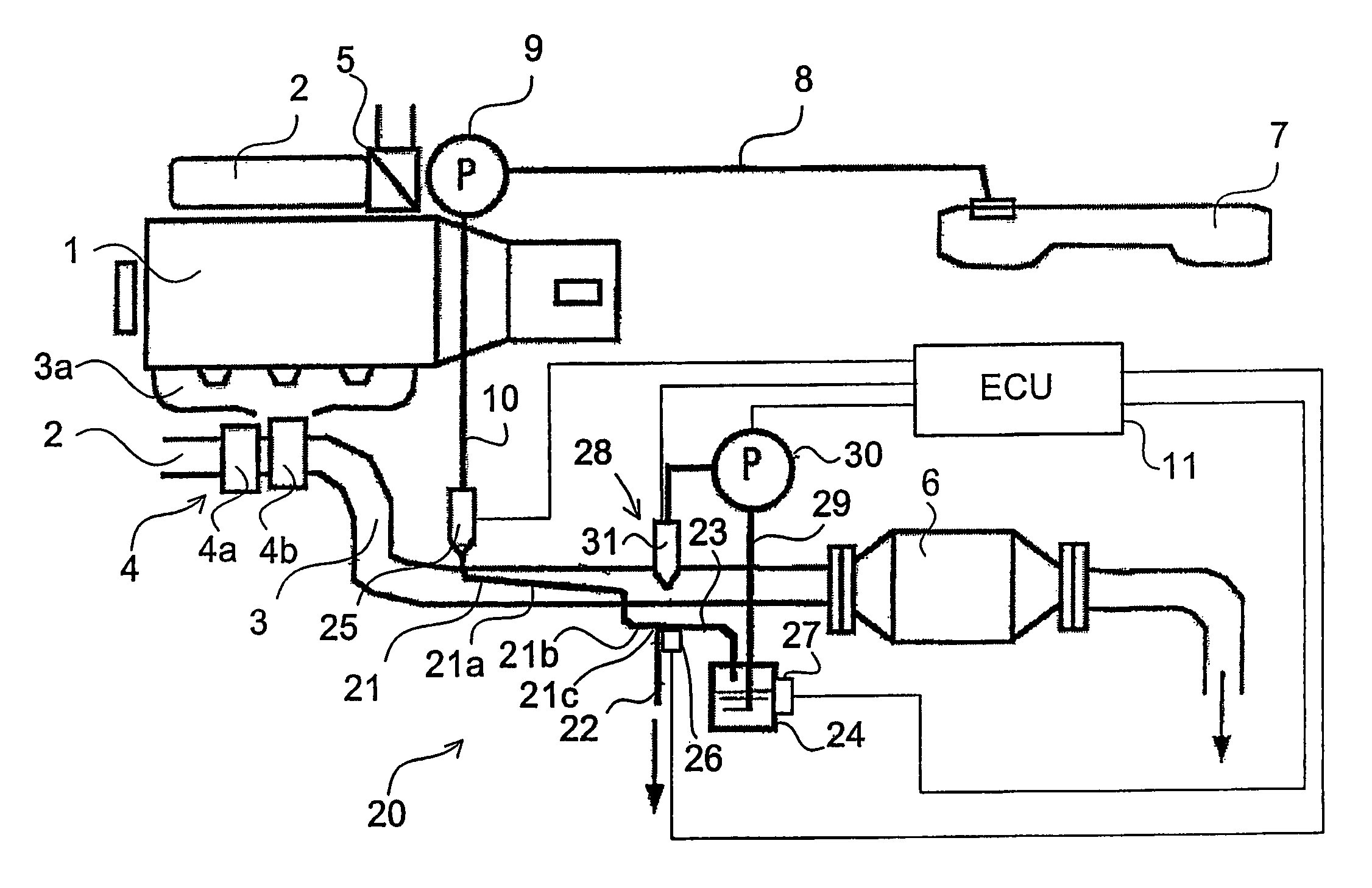
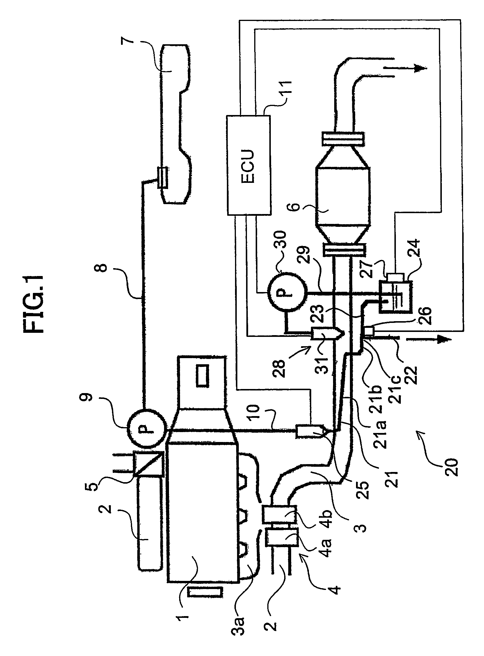
[0035]FIG. 1 shows an embodiment in which a fuel fractionation apparatus according to the present invention is applied to a diesel engine 1 as an internal combustion engine. An intake passage 2 and an exhaust passage 3 are connected to the engine 1. In the intake passage 2, there are provided a compressor 4a of a supercharger 4 which increases an intake pressure by utilizing an exhaust energy, and a throttle valve 5 for adjusting volume of intake air, and there are provided in a side of the exhaust passage 3 a turbine 4b of the supercharger 4 arranged in a downstream side of a manifold 3a, and an exhaust gas purifying apparatus 6 arranged in a downstream side from the turbine 4b, respectively. The exhaust gas purifying apparatus 6 is a known structure in which an occlusion-reduction type NOx catalyst material is carried, for example, by a filter substrate for collecting particulate. In this case, an aspect of the occlusion of NOx is not limited as far as NOx can be held.

[0036]The en...

second embodiment

[0052]The second embodiment according to the present invention is shown in FIG. 5. In this case, in the present embodiment, the same reference numerals are attached to the common parts with the first embodiment, and a detailed description thereof will be omitted. In the present embodiment, the exhaust gas purifying apparatus 6 is provided comparatively near the turbine 4b, and the fractionation section 21a is provided so as to pass through the exhaust passage 3 in the downstream side of the exhaust gas purifying apparatus 6. Further, the adding injector 31 is provided in the manifold 3a. In the present embodiment, the NOx occlusion-reduction type catalyst is controlled and operated at 250 to 400° C. so as to effectively function. Accordingly, it is easy to control the temperature of the branch point 21c to the fractionation temperature 220° C. so as to obtain the fractionated fuel containing no sulfur.

third embodiment

[0053]The third embodiment according to the present invention is shown in FIG. 6. Further, FIGS. 7A and 7B show views obtained by enlarging a part of the fractionation apparatus 20 in FIG. 6. In this case, FIG. 7A shows a plan view of the cylinder head 1a of the internal combustion engine 1 in FIG. 6, and FIG. 7B shows a view in the case of seeing a cross section of the cylinder head 1a along a line VII-VII in FIG. 7A from a side of the manifold 3a. In this case, in the present embodiment, the same reference numerals are attached to the common portions with those of the first embodiment, and a detailed description thereof will be omitted. As is apparent from FIGS. 6, 7A and 7B, the present embodiment is different from the other embodiments in points that the fractionation passage 21 is arranged within the cylinder head 1a corresponding to the engine main body surrounding the combustion chamber of the engine 1, and a pressure reducing pump 32 is provided as a pressure regulating devi...


PUM


Abstract

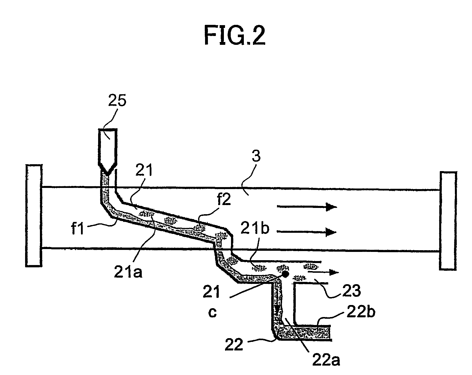
A fuel fractionation method which can suitably control a state of a fuel at a time of fractionating the fuel in an internal combustion engine, which includes the steps of applying an operation for promoting a fractionation of a fuel of an engine to a fractionation passage while making the fuel flow to the fractionation passage, thereby fractionating the fuel into a gas phase fuel and a liquid phase fuel within the fractionation passage, conducting the fractionated gas phase fuel and the fractionated liquid phase fuel to a branch point of the fractionation passage, and separating the gas phase fuel and the liquid phase fuel to a gas phase passage and a liquid phase passage, respectively due to gravity.

Description

TECHNICAL FIELD[0001]The present invention relates to a fuel fractionation method and a fuel fractionation apparatus for an internal combustion engine.BACKGROUND ART[0002]There has been known an exhaust gas purifying apparatus which heats a fuel accumulated around an exhaust pipe of an internal combustion engine by an exhaust heat so as to fractionate the fuel into a light component in a gas phase and a heavy component in a liquid phase, and supplies the fractionated light component as a reducing agent to an NOx occlusion-reduction type catalyst so as to reduce the NOx discharged by the catalyst (refer to JP 3093905 B). In addition, there are publications of JP 2850547 B, JP 11-210447 A and JP 2001-193525 as documents related to the present invention.DISCLOSURE OF THE INVENTION[0003]In the conventional apparatus mentioned above, since a lot of fuel is accumulated around the exhaust pipe, a fuel temperature responds poorly to an exhaust gas temperature change, and there is a case whe...

Claims


Application Information

Patent Timeline
Patent Type & Authority Patents(United States)
IPC IPC(8): F01N3/00F01N5/02F01N3/08F01N3/20F01N3/36F02B37/00F02M1/16F02M31/18
CPCF01N3/0842F01N3/208F01N3/36F02B37/00F02M1/165F02M31/183F01N2240/30F01N2610/03F01N2610/10F01N2900/1811Y02T10/144Y02T10/126Y02T10/24Y02T10/12
Inventor UEDA, TAKANORIHIROTA, SHINYA
Owner TOYOTA JIDOSHA KK
Learn More