Valve clearance adjusting method

a valve mechanism and valve clearance technology, applied in the direction of valve arrangements, mechanical equipment, machines/engines, etc., can solve the problem of temporary valve clearance out of the allowable range, and achieve the effect of accurate and easy adjustmen

Active Publication Date: 2020-04-07
SANYO KIKO KK
View PDF5 Cites 1 Cited by
  • Summary
  • Abstract
  • Description
  • Claims
  • Application Information

AI Technical Summary

Benefits of technology

[0005]Thus, an object of the present invention is to provide a valve clearance adjusting method by which an accurate valve clearance adjustment can easily be performed regardless of the tolerance of pitch dimensions of an adjusting screw.
[0007]According to the aspect of the present invention, it is enough to perform the cam profile measurement only once. In addition, the valve clearance can be accurately and easily adjusted regardless of the tolerance of pitch dimensions of the adjusting screw.

Problems solved by technology

Therefore, if the tolerance of the pitch dimensions is large, the temporary valve clearance is out of the allowable range.

Method used


Image

  • Valve clearance adjusting method
  • Valve clearance adjusting method
  • Valve clearance adjusting method

Examples


Embodiment Construction

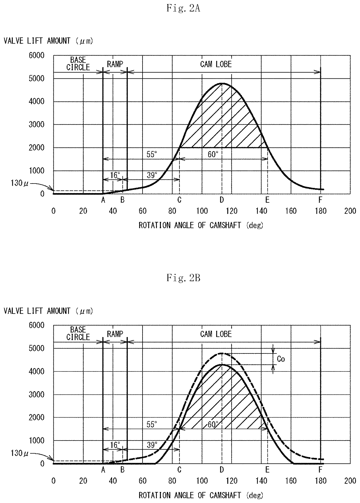
[0015]Hereinafter, an embodiment according to the present invention will be described with reference to the drawings. The same reference number is assigned to the same or corresponding element in each of the drawings, and overlapping descriptions of the same or corresponding element are omitted. A valve clearance adjusting method according to the embodiment of the present invention is a method of easily and accurately adjusting a valve clearance with use of a lift amount of a cam profile.

(Overview of Cylinder Head)

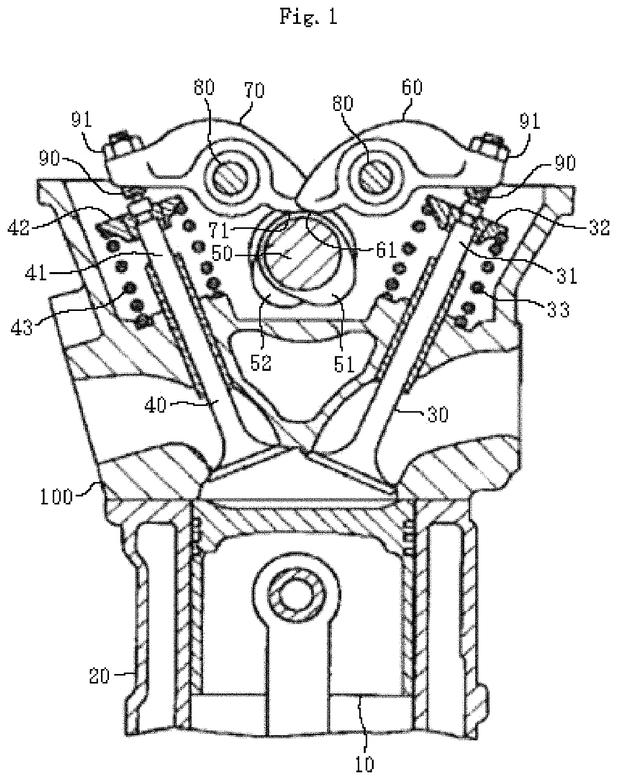
[0016]FIG. 1 is a schematic view of an SOHC (Single Over Head Camshaft) cylinder head 100 to which the valve clearance adjusting method according to the embodiment of the present invention can be applied. The cylinder head 100 including an intake valve 30 and an exhaust valve 40 is mounted on a cylinder block 20 in which a piston 10 is housed. Valve retainers 32, 42 are respectively attached to end portions of valve stems 31, 41, and the valve retainers 32, 42 are respecti...


PUM


Abstract

Provided is a valve clearance adjusting method by which an accurate valve clearance adjustment can be easily performed regardless of the tolerance of pitch dimensions of an adjusting screw. The valve clearance adjusting method including: measuring a cam profile of the camshaft 50 mounted on the cylinder head100; identifying, on the basis of a measurement result of the cam profile, a predetermined rotation angle θV of the camshaft 50 at which a predetermined lift amount corresponding to a predetermined valve clearance is obtained; rotating the camshaft 50 and allowing a pressed portion 61, 71 of the rocker arm 60, 70 to face a cam surface at the predetermined rotation angle θV; rotating an adjusting screw 90 with the pressed portion faced with the cam surface and setting a valve clearance to zero; and fastening the adjusting screw 90 with a lock nut 91.

Description

BACKGROUND OF THE INVENTION(1) Field of the Invention[0001]The present invention relates to a valve clearance adjusting method for a valve mechanism and, in particular, to a valve clearance adjusting method for a valve mechanism configured to transmit driving force from a camshaft via a rocker arm to a valve.(2) Description of Related Art[0002]A valve mechanism, such as an OHV (Over Head Valve) valve mechanism, an OHC (Over Head Camshaft) valve mechanism, and a DOHC (Double Over Head Camshaft) valve mechanism, for an internal combustion engine is configured to transmit driving force from a camshaft via a rocker arm to a valve. In the case of adjusting a valve clearance in such a valve mechanism, a thickness gauge is interposed in a clearance between the valve and the rocker arm or in a clearance between the camshaft and the rocker arm and the thickness gauge is tightened with an adjusting screw; thereby the valve clearance is adjusted. If it is not allowed to use the thickness gauge...

Claims


Application Information

Patent Timeline
Patent Type & Authority Patents(United States)
IPC IPC(8): F01L1/20F01L1/053F01L1/18
CPCF01L1/181F01L1/20F01L1/185F01L1/053F01L2820/01F01L2103/01F01L2001/0537F01L2105/00F01L2001/0535F01L2303/01F01L2305/00
Inventor TAKAGI, YOSHIAKI
Owner SANYO KIKO KK
Why Eureka
Try Eureka