Equipment for controlling distance between inductor and raceway in quenching of slewing bearing raceway

A slewing bearing and distance control technology, which is applied in the direction of quenching device, heat treatment equipment, heat treatment process control, etc., can solve the problems of deposition, hardness of raceway hardened layer, uneven depth distribution, and distance can not always be kept consistent, etc., to achieve Guaranteed quality and precise adjustment effect

Pending Publication Date: 2022-07-08
安徽文君自动化科技股份有限公司
View PDF0 Cites 0 Cited by
  • Summary
  • Abstract
  • Description
  • Claims
  • Application Information

AI Technical Summary

Problems solved by technology

[0006] Aiming at the deficiencies of the prior art, the present invention provides a slewing bearing raceway quenching device for controlling the distance between the inductor and the raceway, which can accurately adjust the gap between the sensor and the raceway to ensure that the slewing bearing raceway is hardened. The advantage of the quality of the hard layer solves the problem that when the raceway is quenched, the distance between the workpiece rotation quenching sensor and the raceway cannot always be kept consistent, resulting in uneven distribution of hardness and depth of the hardened layer of the raceway, and precipitation Accumulation phenomenon, problems that affect product quality

Method used


Image

  • Equipment for controlling distance between inductor and raceway in quenching of slewing bearing raceway
  • Equipment for controlling distance between inductor and raceway in quenching of slewing bearing raceway
  • Equipment for controlling distance between inductor and raceway in quenching of slewing bearing raceway

Examples


Embodiment Construction

[0022] The technical solutions in the embodiments of the present invention will be clearly and completely described below with reference to the accompanying drawings in the embodiments of the present invention. Obviously, the described embodiments are only a part of the embodiments of the present invention, rather than all the embodiments. Based on the embodiments of the present invention, all other embodiments obtained by those of ordinary skill in the art without creative efforts shall fall within the protection scope of the present invention.

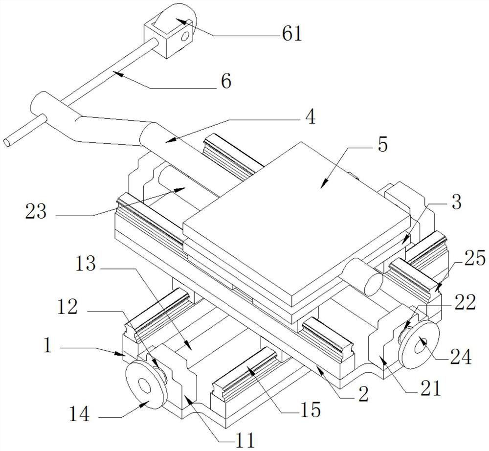
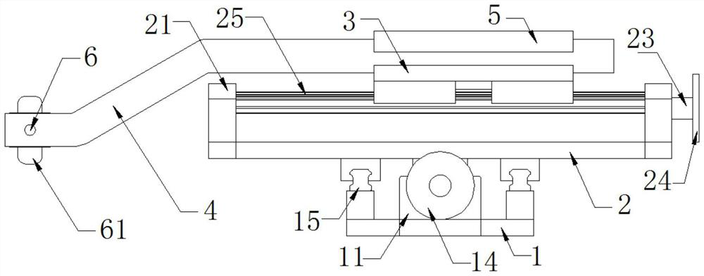
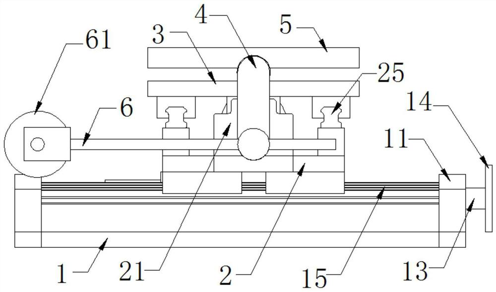
[0023] see Figure 1-3 , the slewing bearing raceway quenching is used for the distance control equipment between the inductor and the raceway, including the longitudinal base 1, the transverse base 2 and the sliding table 3, the front and back of the longitudinal base 1 are fixedly installed with longitudinal limit blocks 11, A longitudinal through hole 12 is provided in the center position of the longitudinal limit block 11, the in...


PUM


Abstract

The invention relates to the technical field of slewing bearing raceway quenching, and discloses slewing bearing raceway quenching equipment for controlling the distance between an inductor and a raceway, the slewing bearing raceway quenching equipment comprises a longitudinal base, a transverse base and a sliding table, longitudinal limiting blocks are fixedly installed on the front face and the back face of the longitudinal base, and longitudinal through holes are formed in the centers of the longitudinal limiting blocks; a longitudinal adjusting shaft is movably installed on the inner wall of the longitudinal through hole, the longitudinal adjusting shaft is driven to move through a longitudinal adjusting hand wheel arranged on the front face of the longitudinal adjusting shaft, then the coupling gap between the sensor and the gear is adjusted, and the transverse adjusting shaft is driven to move through a transverse adjusting hand wheel arranged on the right side of the transverse adjusting shaft. And the guide wheel arranged on the left side of the guide wheel bracket is put into the track, so that the inductor can stably move along the adjusted gap, and the effects of accurately adjusting the gap between the inductor and the roller path and ensuring the quality of a hardening layer of the slewing bearing roller path are achieved.

Description

technical field [0001] The invention relates to the technical field of slewing bearing raceway quenching, in particular to slewing bearing raceway quenching used for distance control equipment between an inductor and a raceway. Background technique [0002] As one of the main accessories of construction machinery, slewing bearing is used in machinery and equipment such as tower cranes, cranes, excavators, construction industry and shipbuilding industry. Due to the particularity of its structure, the quality of the slewing bearing directly affects the service life of the main engine, and the service life of the slewing bearing mainly depends on the quality of the hardened layer of the bearing raceway. [0003] When the raceway is quenched, the distance between the raceway and the quenching inductor cannot always be consistent when the workpiece is rotated, resulting in uneven distribution of hardness and depth of the hardened layer of the raceway, and deposition, which affect...

Claims


Application Information

Patent Timeline
IPC IPC(8): C21D1/62C21D1/10C21D9/40C21D11/00
CPCC21D1/62C21D1/10C21D9/40C21D11/00Y02P10/25
Inventor 张卫军
Owner 安徽文君自动化科技股份有限公司
Why Eureka
Try Eureka