
Clacking ball toy

a technology of clacking ball and toy, which is applied in the field can solve the problems of clacking ball toy having serious safety flaws, unable to withstand the force of clacking ball striking one another for prolonged periods of time, and lack of original “clacking” sound, etc., to reduce the potential for injury from a moving sphere

Active Publication Date: 2020-04-14
PENA DANIEL
View PDF7 Cites 1 Cited by
  • Summary
  • Abstract
  • Description
  • Claims
  • Application Information

AI Technical Summary

Benefits of technology

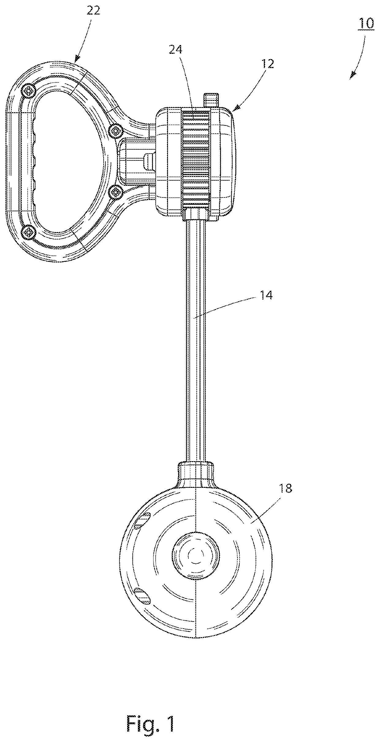
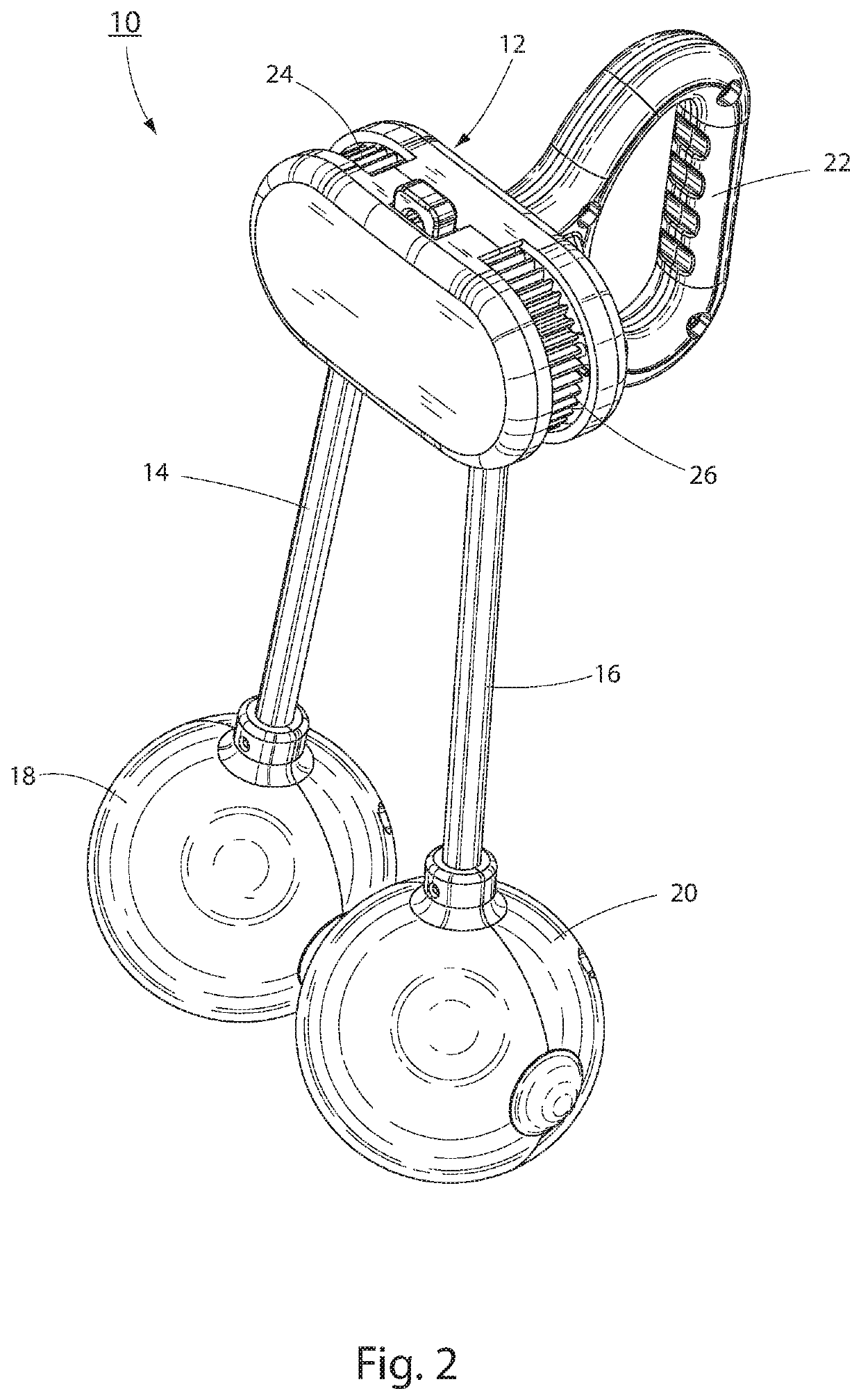
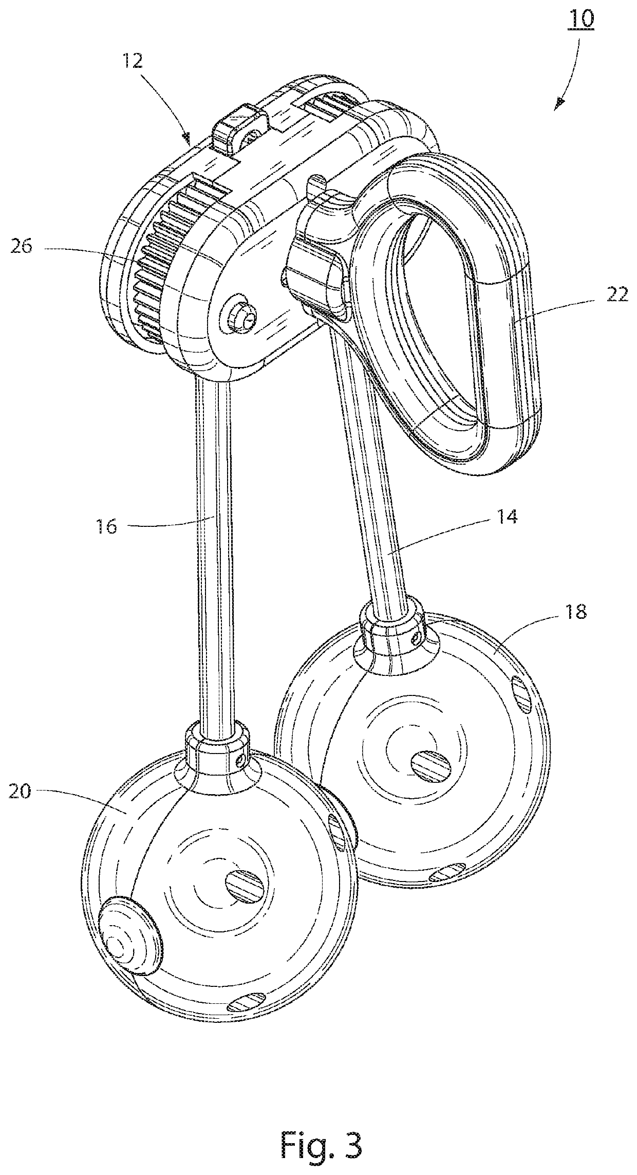
The patent describes a clacker ball toy that has a housing, a handle, and two rods that pivot inside the housing. There is also a sphere attached to the end of each rod, at a point away from the housing. These rods and spheres are connected in a way that allows them to move together when the toy is being played with. The rods and spheres are mounted in a way that allows them to move in an arcuate path relative to the housing, and they also move in a common plane. This means that the spheres will hit each other at the highest points in the air, without moving in a different direction than the user. In some versions of the toy, the spheres have LED lights that will light up when the toy is played with.

Problems solved by technology

Despite these attributes, the clacker type toy had some serious safety flaws.
A hidden, and more serious safety issue with the clacker type toy was that the material used to make the spheres (acrylic) could not withstand the force of the spheres striking one another for prolonged periods of time.
As a consequence, the spheres would eventually shatter, sending small pieces of hard plastic flying in every direction, causing serious injury.
It does, however, lack the characteristic “clacking” sound of the original.
However, the plastic spheres in the new versions—unlike the original—are shatterproof.
However, with these versions, because the spheres are hard and attached to string, there is a potential for injury from being struck by one or both of the moving spheres.
Finally, none of these toys were appropriate for use in the dark, an operating environment experimented with by numerous children over the years.

Method used


Image

  • Clacking ball toy
  • Clacking ball toy
  • Clacking ball toy

Examples


first embodiment

[0029]In a first embodiment as shown in FIG. 8, while only the interior components of sphere 18 are illustrated, it should be understood that the interior components of sphere 20 are identical thereto. As shown magnet 90 is positioned within housing 88 of sphere 18, preferably oriented with a south pole (positive or + pole) allowing a magnetic field to establish a repulsive effect on the opposing south pole (positive or + pole) of a magnet (not shown) contained within the opposing sphere 20, producing equivalent fields of energy inducing the repelling force on each sphere. The energy field generated at each sphere's 180° down rotation between grommets 100 and 102 and during the sphere's 180° up rotation between grommets 98 and 104 is representative of a field of magnetism where both magnets contacting each other are urged away from each other and forcing the respective magnets through respective cavities in housings 88 located in spheres 18, 20. Illustrated in FIG. 8, spheres 18 and...

second embodiment

[0033]In a second embodiment, shown in FIG. 7, the LED devices 80 are powered by the aforementioned electromagnetism, or in the alternative, a conventional battery powered circuit. The spheres 18, 20 contain the transistor, capacitor 84 and optionally a battery 96 contained within compartment 86. The type of battery used is not particularly critical, and can be a standard A, AA, or AAA size battery or a so-called button cell battery. Alternatively, one or more battery compartments 86 may be located within the handle 22 or the housing 12 or both. In FIG. 7, switch 82 is positioned horizontally to deactivate the LED consumption, turning the device off, but centripetal force or movement of the sphere turns the device on, and while in use actuates the illumination device. The switch may be a motion activated switch or may be manually operated and located, for example, on the handle 22 or housing 12. Although not shown, as would be understood another alternative power source such as phot...


PUM


Abstract

A clacker ball toy having a housing, a handle attached to the housing, a pair of rods pivotally mounted to the housing, and a sphere attached to an end of each rod at a location remote from the housing, wherein the rods are operatively interconnected to one another so as to move together and in unison with one another, the rods and spheres being mounted such that they can move in a circumferential arc relative to the housing and also move in a common plane, whereby the spheres will strike each other at apex points within the common plane above and below the housing. In the embodiments, the spheres contain an LED device which will illuminate during use of the toy.

Description

FIELD OF THE INVENTION[0001]The invention herein pertains to a clacking ball toy, and more particularly pertains to a clacking ball toy with improved safety features that also generates electricity for illumination during use, with or without the need of batteries.DESCRIPTION OF THE PRIOR ART AND OBJECTIVES OF THE INVENTION[0002]During the late 1960's and 1970's, a particular children's toy was very popular in the marketplace. This toy, known and sold under various brand names such as “Clackers”, Klick Klaks”, “Ker Bangers”, “Knockers”, “Kbonger”, “Ker-Knockers”, “Whak-Ko's” and other names consisted of two spheres attached to opposite ends of a length of string. Mid-way between the spheres and attached to the string was a ring, rod or other grip element.[0003]In use, a child would hold the ring / grip element and allow the spheres to hang. Using a gentle motion of the hand to start would cause the spheres to swing outward and then back to center in a pendulum motion. As the spheres r...

Claims


Application Information

Patent Timeline
IPC IPC(8): A63H31/00A63H33/00
CPCA63H33/00A63H31/00A63H5/00A63H33/22A63H33/26
Inventor PENA, DANIEL
Owner PENA DANIEL
Learn More