Damper

a technology of adampers and cylinders, applied in the field of adampers, can solve the problems of increasing the number of components, increasing so as to prevent the damage of the oil seal, increase the number of attachments, and reduce the number of parts

Active Publication Date: 2020-04-21
KYB CORP
View PDF25 Cites 1 Cited by
  • Summary
  • Abstract
  • Description
  • Claims
  • Application Information

AI Technical Summary

Benefits of technology

[0003]The conventional damper includes the oil seal on the lower side, the action chamber side of the rod guide. Therefore, a foreign matter from the external air side is difficult to reach the oil seal, thereby ensuring restraining a damage of the oil seal. However, in the case where a dust seal to prevent a mixture of a foreign matter is installed to an upper side of the rod guide in addition to the conventional damper configuration, the number of components increases, making assembly work complicated. In the conventional configuration, to cover a rod insertion side opening on a tubular member such as the cylinder in the damper, the oil seal, the dust seal, and the outer peripheral seal need to be individually attached. This increases the number of attachments, making the assembly work complicated.
[0004]Furthermore, in the conventional damper, to install the outer peripheral seal, an annular groove with U shape in cross section needs to be formed on an outer periphery of the rod guide. This makes a shape of the rod guide complicated, increasing a processing cost for the rod guide.
[0005]An object of the present invention is to provide a damper that ensures simplifying assembly work and reducing a processing cost for a rod guide even in the case where the damper includes an oil seal on an action chamber side of the rod guide, a dust seal on a side of the rod guide opposite to the action chamber, and further an outer peripheral seal.

Problems solved by technology

Therefore, a foreign matter from the external air side is difficult to reach the oil seal, thereby ensuring restraining a damage of the oil seal.
However, in the case where a dust seal to prevent a mixture of a foreign matter is installed to an upper side of the rod guide in addition to the conventional damper configuration, the number of components increases, making assembly work complicated.
This increases the number of attachments, making the assembly work complicated.
This makes a shape of the rod guide complicated, increasing a processing cost for the rod guide.

Method used


Image

  • Damper
  • Damper
  • Damper

Examples


Embodiment Construction

[0013]The following describes a damper according to an embodiment of the present invention with reference to the drawings. Like reference numerals designate corresponding or identical elements throughout some drawings.

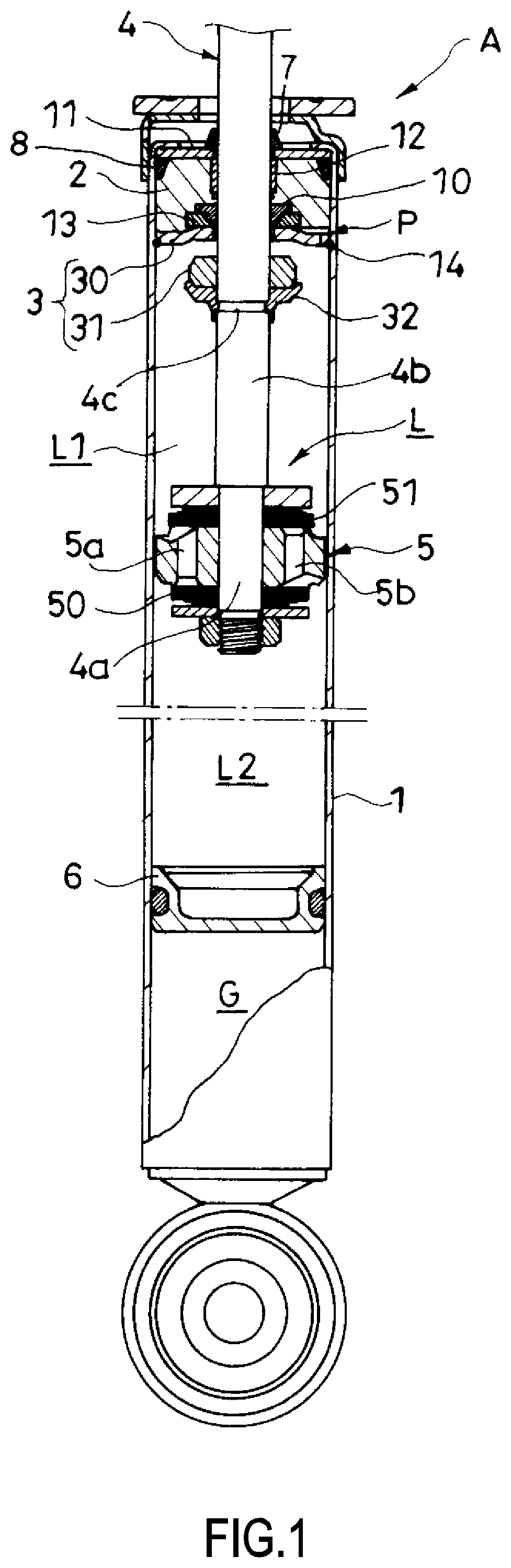
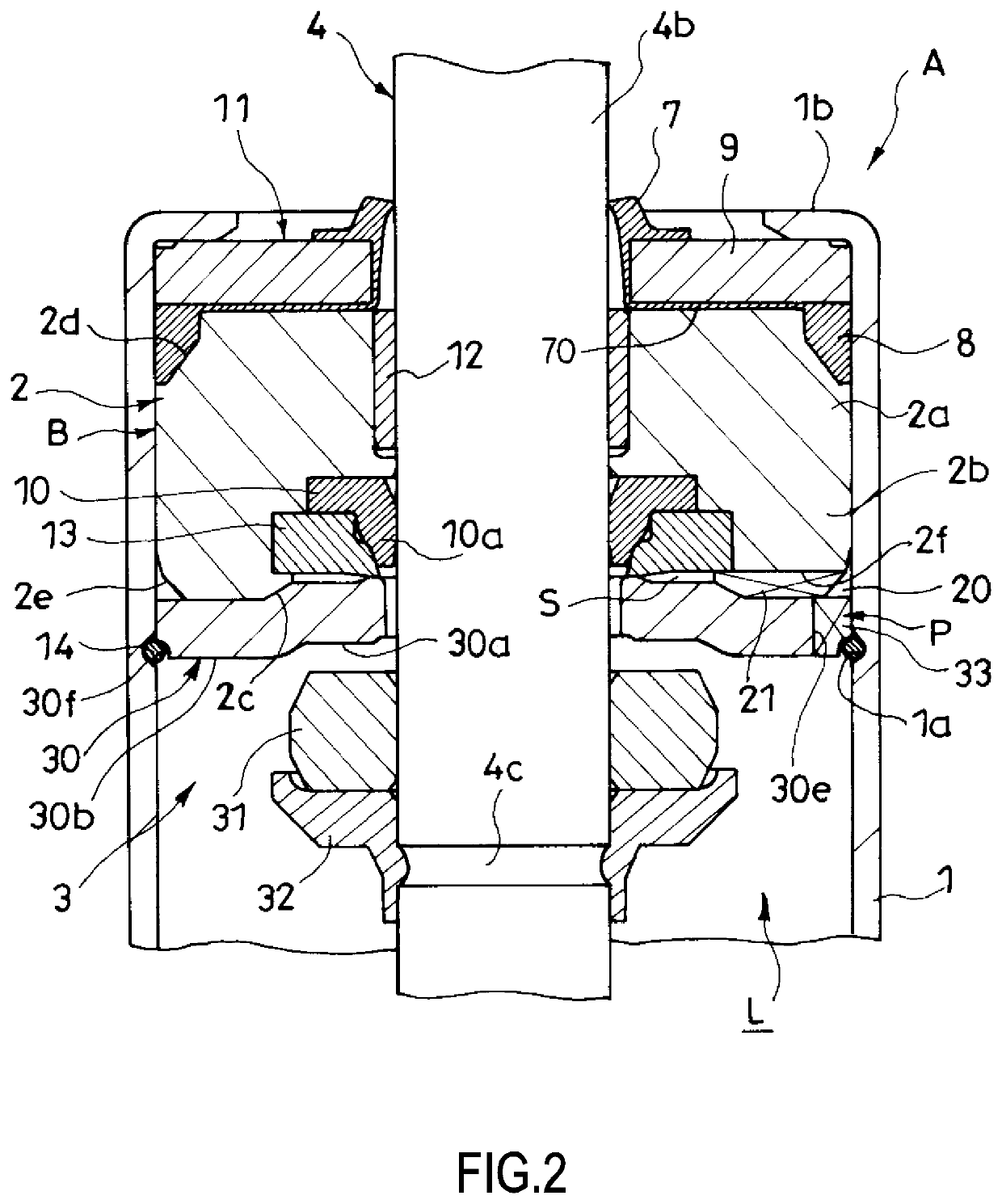
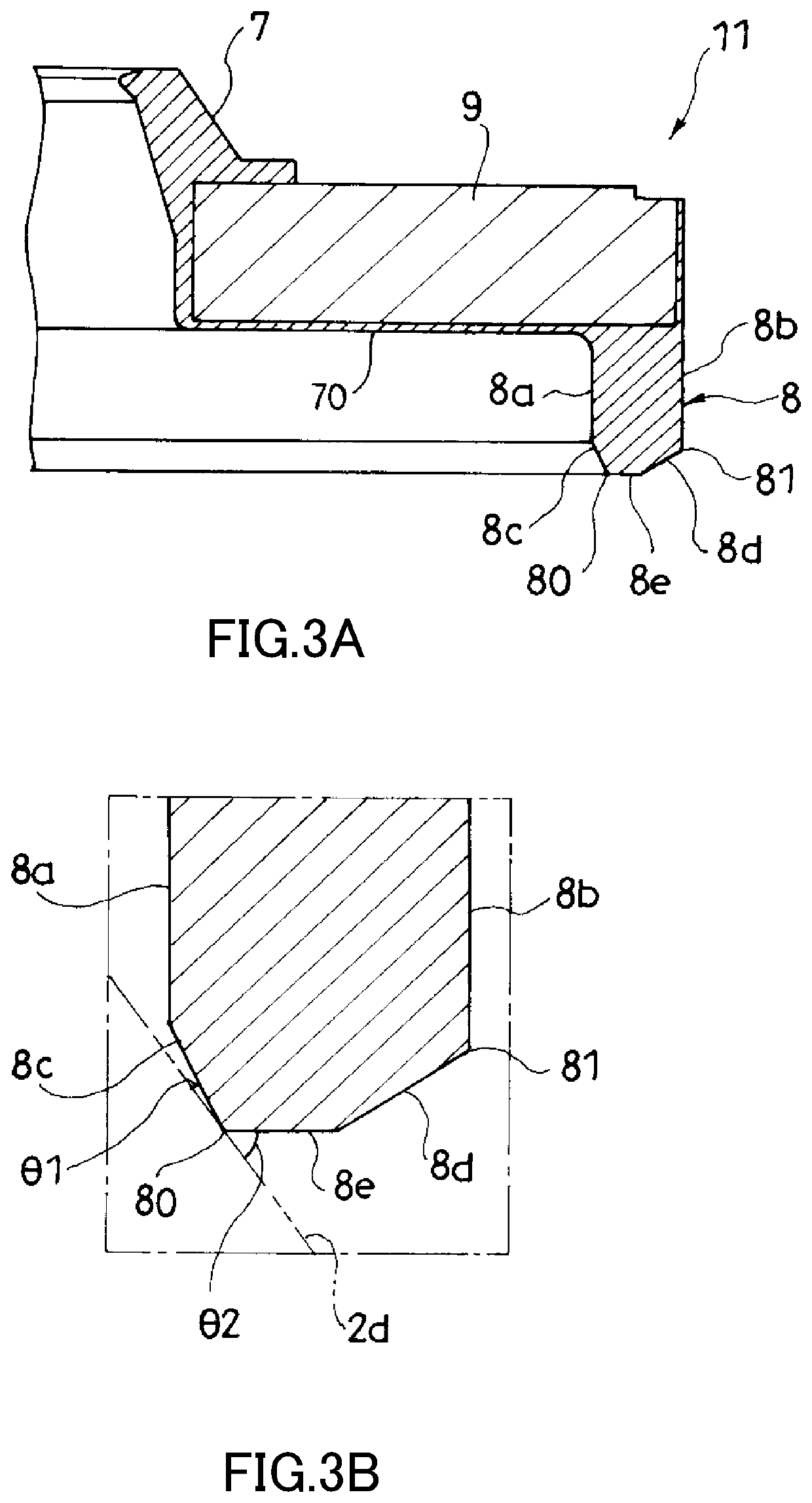
[0014]As illustrated in FIG. 1 and FIG. 2, a damper A according to the embodiment includes a cylinder (a tubular member) 1, an annular rod guide 2, a rod 4, an oil seal 10, and a sealing member 11. The cylinder 1 internally forms an action chamber L. The rod guide 2 is secured to one side opening of this cylinder 1. The rod 4 is inserted through an inside of the rod guide 2 so as to be axially movable. The oil seal 10 is installed to the action chamber L side of the rod guide 2 to seal an outer periphery of the rod 4. The sealing member 11 is stacked on an opposite side of the rod guide 2 to the action chamber L. The sealing member 11 includes a dust seal 7 and an outer peripheral seal 8. The dust seal 7 seals an outer periphery of the rod 4. The outer peripheral seal ...


PUM


Abstract

A damper includes a tubular member that internally forms an action chamber, an annular rod guide secured to one side opening of the tubular member, a rod inserted through an inside of the rod guide so as to be axially movable, an oil seal installed to the action chamber side of the rod guide and seal an outer periphery of the rod, and a sealing member stacked on a side of the rod guide opposite to the action chamber, wherein the sealing member includes a dust seal that seals the outer periphery of the rod, and an outer peripheral seal that seals a gap between the tubular member and the rod guide.

Description

TECHNICAL FIELD[0001]The present invention relates to a damper.BACKGROUND ART[0002]A damper is used to damp vibrations of, for example, a vehicle, a device, and a construction. For example, a damper disclosed in FIG. 3 in DE3018215A1 includes a cylinder, an annular rod guide, a rod, an annular oil seal, and an annular outer peripheral seal. The cylinder internally forms an action chamber. The rod guide is secured to an upper opening of this cylinder. The rod is inserted through an inside of the rod guide so as to be axially movable. The oil seal is installed to a lower side of the rod guide. The outer peripheral seal is fitted to an annular groove formed on an outer periphery of the rod guide. The oil seal seals an outer periphery of the rod. The outer peripheral seal seals between the rod guide and the cylinder. This prevents a fluid in the action chamber from leaking to an external air side.SUMMARY OF INVENTION[0003]The conventional damper includes the oil seal on the lower side, ...

Claims


Application Information

Patent Timeline
Patent Type & Authority Patents(United States)
IPC IPC(8): F16F9/36F16F9/32F16F9/06
CPCF16F9/362F16F9/32F16F9/061
Inventor TAKEUCHI, HIDEAKI
Owner KYB CORP
Why Eureka
Try Eureka