Exhaust air channel arrangement for a kitchen exhaust air channel system

a technology of exhaust air channel and exhaust air, which is applied in ventilation systems, lighting and heating apparatus, heating types, etc., can solve the problems of limited, limited, and achieve the effect of reducing the risk of injuries

Active Publication Date: 2020-04-28
NABER HOLDING GMBH & CO KG
View PDF13 Cites 0 Cited by
  • Summary
  • Abstract
  • Description
  • Claims
  • Application Information

AI Technical Summary

Benefits of technology

[0003]The object of the invention is thus to propose an exhaust air channel arrangement of above said type, which has very small wall thicknesses and a high mechanical strength.
[0008]The supporting structure may in particular be a formed integral metal sheet stripe, thus being economical to manufacture.
[0013]The supporting structure may thus have a geometry, which is adapted for doubling the inner circumference of the sheet metal pipe over a substantial portion and thus correspondingly increase the mechanical strength of the sheet metal pipe.
[0020]In order to facilitate the mounting of the supporting structures inside the sheet metal pipe, the supporting structure may be provided, on its outer circumference, with a smooth surface, at least on the part of the same which contacts the inner circumference of the sheet metal pipe. This allows the supporting structure to be comfortably inserted over opposed front sides of the sheet metal pipe.
[0022]The inventive exhaust air channel arrangement in particular allows the sheet metal pipe to be manufactured with a thin metal sheet. The thickness of the thin metal sheet may be less than 0.5 mm, preferably even less than 0.4 mm and preferably less than 0.3 mm. Fundamentally, it is also possible that the sheet metal pipe and the supporting structure are made with a thicker sheet metal, such as one having a thickness of 0.8 mm. Depending on the application, however, in the case of a sheet metal pipe having a thickness of 0.8 mm, and more, the use of a supporting structure may be omitted, or the structure may be lightweight.
[0023]The use of thin metal sheet has, on the other hand, the drawback, that in case of a shortening of the sheet metal pipe, sharp cutting edges are formed, which may cause injuries. In order to reduce the risk of injuries on the sharp cutting edges of the sheet metal pipe, when the sheet metal pipe is provided, on the front side of at least one of its opposed ends, with a sharp cutting edge, this cutting edge is covered by a mounting sealing which is inserted over the sharp cutting edge on the at least one end of the sheet metal pipe. The mounting sealing may have a U-shaped cross-section. Moreover, the mounting sealing may have at least one enveloping sealing lip on its inner circumference. In one embodiment, the mounting sealing may seal a female connection with respect to an element with a male connection.

Problems solved by technology

This, however, is limited by the fact that the exhaust air channel arrangement is required to have a certain minimum mechanical strength, on one hand in order to ensure a fluidic durable sealed connection of the individual components at the connection points, and, on the other hand, to allow the exhaust air channel arrangement to also have a certain tread resistance, for example when it has to be mounted inside or on the floor of a building.

Method used


Image

  • Exhaust air channel arrangement for a kitchen exhaust air channel system
  • Exhaust air channel arrangement for a kitchen exhaust air channel system
  • Exhaust air channel arrangement for a kitchen exhaust air channel system

Examples


Embodiment Construction

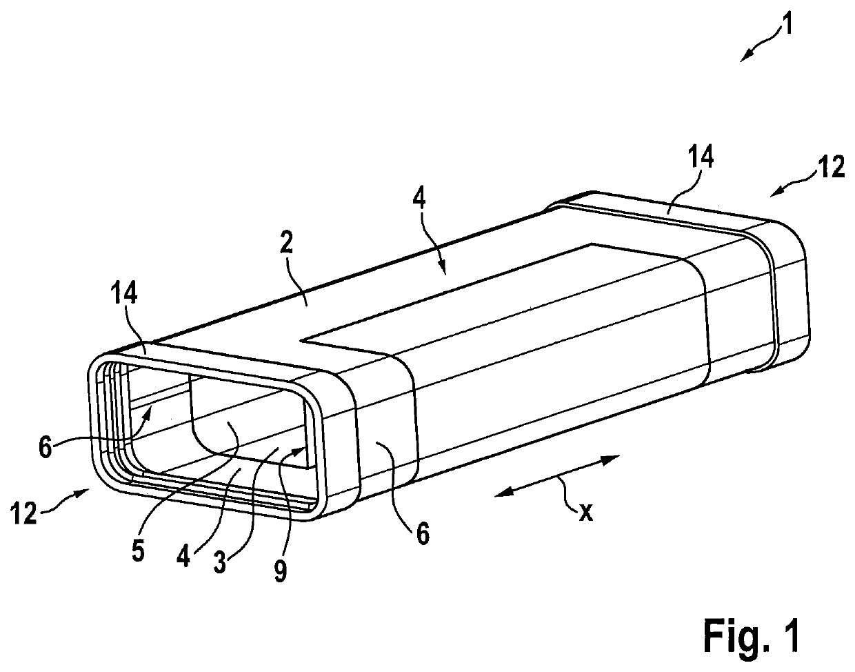
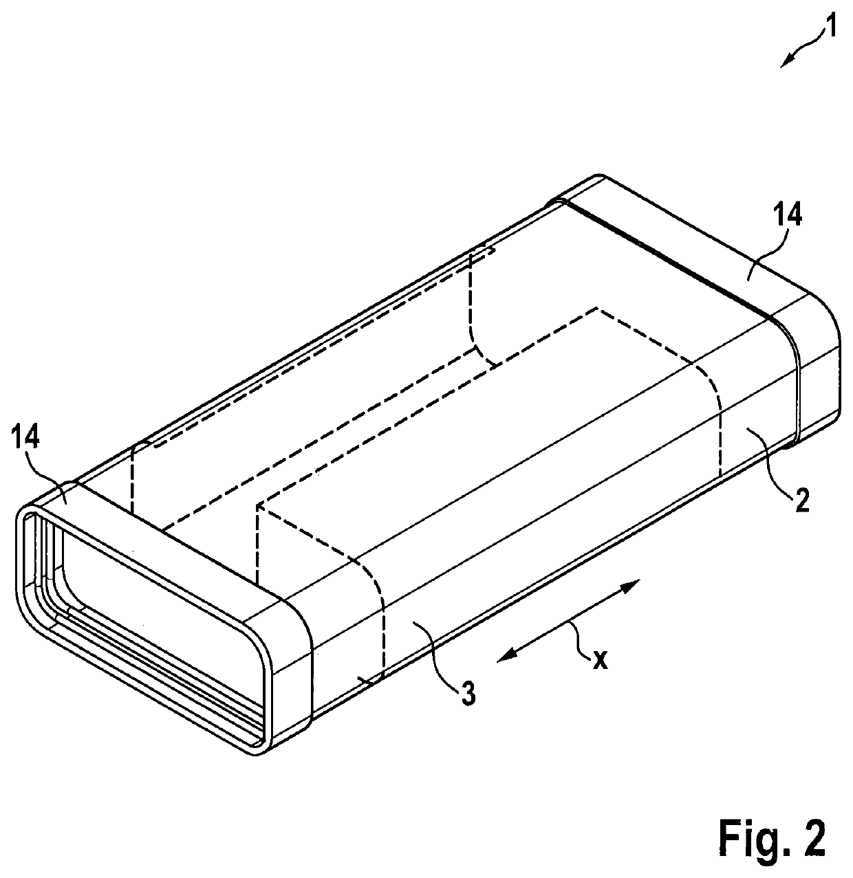
[0030]FIG. 1 shows an exemplary embodiment of an inventive exhaust air channel arrangement 1, as used in kitchen exhaust air channel systems, for example.

[0031]The exhaust air channel arrangement 1 may in particular be entirely made of metal, in particular sheet metal, except for its mounting sealing's 14, which are inserted over the opposed ends, and thus fulfils the highest requirements regarding fire protection.

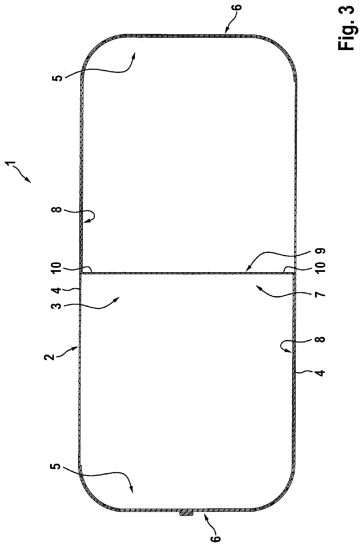
[0032]The sheet metal pipe 2 may be made of thin sheet metal, wherein the supporting structure 3 housed within the sheet metal pipe 2 provides the same with an additional mechanical strength, so that the exhaust air channel arrangement shown reaches at least the mechanical strength of plastic channel arrangements known in the state of the art.

[0033]The supporting structure 3 may also be a formed sheet metal, so that this too may be manufactured, at low costs, and only by bending and folding of thin metal sheets. The supporting structure is a component separate from the she...


PUM


Abstract

An exhaust air channel arrangement for a kitchen exhaust air channel system is provided in which the exhaust air channel arrangement is composed of a sheet metal pipe and a supporting structure, which is movably received within the sheet metal pipe along the longitudinal direction (x) of the sheet metal pipe, wherein both opposed wall portions of the sheet metal pipe are mutually supported by the supporting structure.

Description

BACKGROUND OF THE INVENTION[0001]The present invention is based on an exhaust air channel arrangement for a kitchen exhaust air channel system. Such an exhaust air channel arrangement is known, for example, from JP 4989426 B2. Similar exhaust air channel arrangements are described in U.S. Pat. No. 2,180,644 A, DE 10 2007 034 595 B3 and KR 10-2012-0055214 A.[0002]In particular, in order to fulfill fire protection requirements, in exhaust air channel arrangements of this type, it is frequently desired that these are not configured as plastic material channel systems, as in the state of the art, but are made of metal. In order to reduce as much as possible the higher costs of metal sheet channel systems with respect to plastic channel systems, it is an object to reduce as much as possible the sheet thicknesses of blank materials, from which the individual components of the exhaust air channel arrangement are made. This, however, is limited by the fact that the exhaust air channel arran...

Claims


Application Information

Patent Timeline
Patent Type & Authority Patents(United States)
IPC IPC(8): F24F13/02F16L9/22F16L9/00F16L9/16F24F7/00
CPCF16L9/16F16L9/003F16L9/22F24F13/02F24F13/0245F24F2007/001F24F11/34F24F13/0254F24F7/10E04F17/02B08B15/00B08B15/002
Inventor NABER, HANS-JOACHIM
Owner NABER HOLDING GMBH & CO KG
Why Eureka
Try Eureka