Method for producing a filter element

a filter element and filter element technology, applied in the direction of filtration separation, separation process, manufacturing tools, etc., to achieve the effect of efficient and economical way

Active Publication Date: 2020-05-05
HYDAC FILTERTECHNIK GMBH
View PDF8 Cites 0 Cited by
  • Summary
  • Abstract
  • Description
  • Claims
  • Application Information

AI Technical Summary

Benefits of technology

[0004]An object of the present invention is to provide an improved method permitting production of such filter elements in a very efficient and economical way.

Problems solved by technology

If in operation the filter mat becomes completely clogged with impurities, the filter element has to be changed for a new and unconsumed filter element.

Method used


Image

  • Method for producing a filter element
  • Method for producing a filter element
  • Method for producing a filter element

Examples


Embodiment Construction

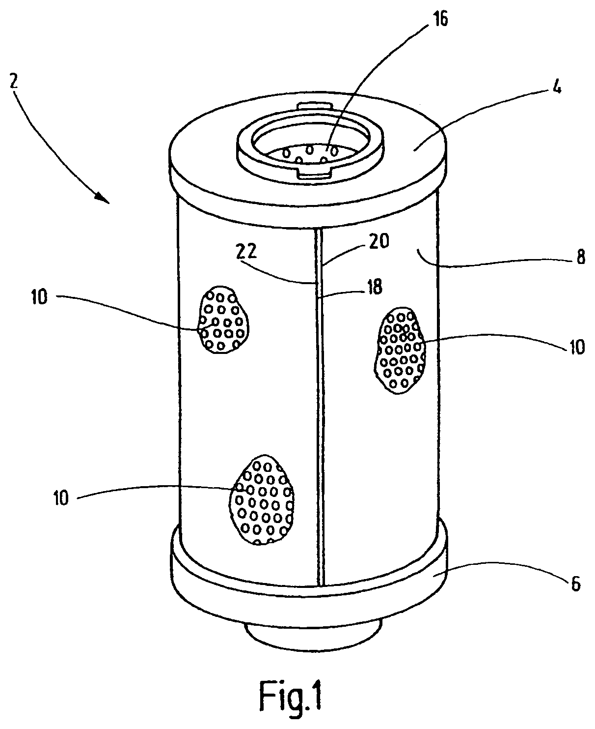
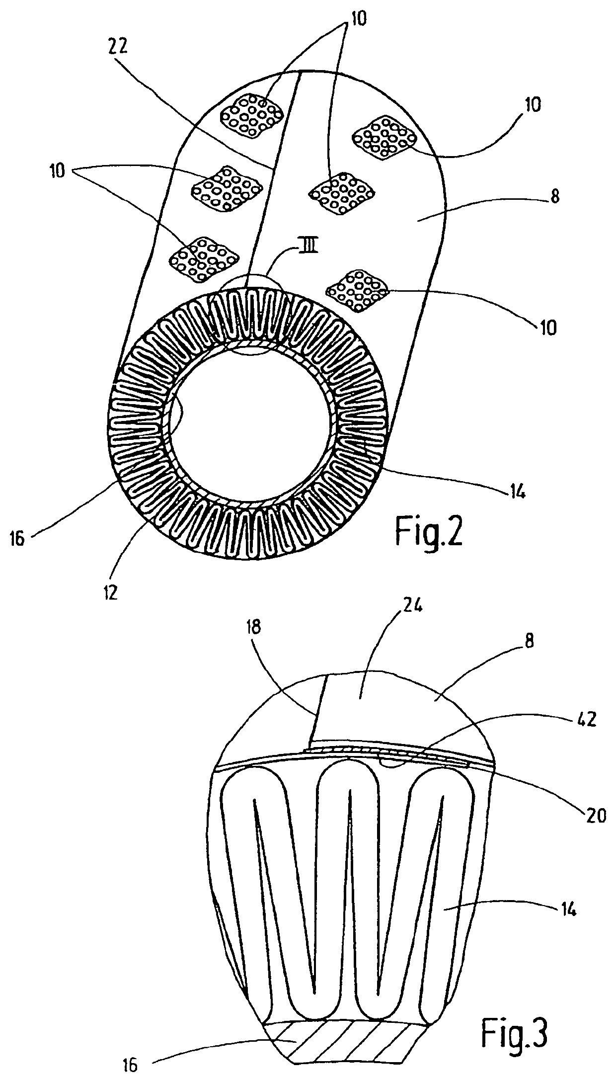
[0021]The filter element 2, depicted in its entirety in FIG. 1, has an outer sleeve made of a perforated film web 8 and located between the end caps 4 and 6. These end caps 4, 6 are injection molded of a synthetic plastic material. The perforation of the film web 8 is indicated only in a few areas 10. The film web 8 surrounds an annular body 12 having a construction that is most easily discernible from FIGS. 2 and 3. As evident, the annular body 12 has a folded filter mat web 14 that is folded in the manner of pleats and that surrounds an inner support tube 16 having fluid openings. FIG. 3 shows that the ends 18 and 20 of the film web 8 are laid one on top of the other, so that an overlapping area 24 is formed. The formed outer sleeve is closed in a longitudinal weld 22 (see FIGS. 1 and 2).

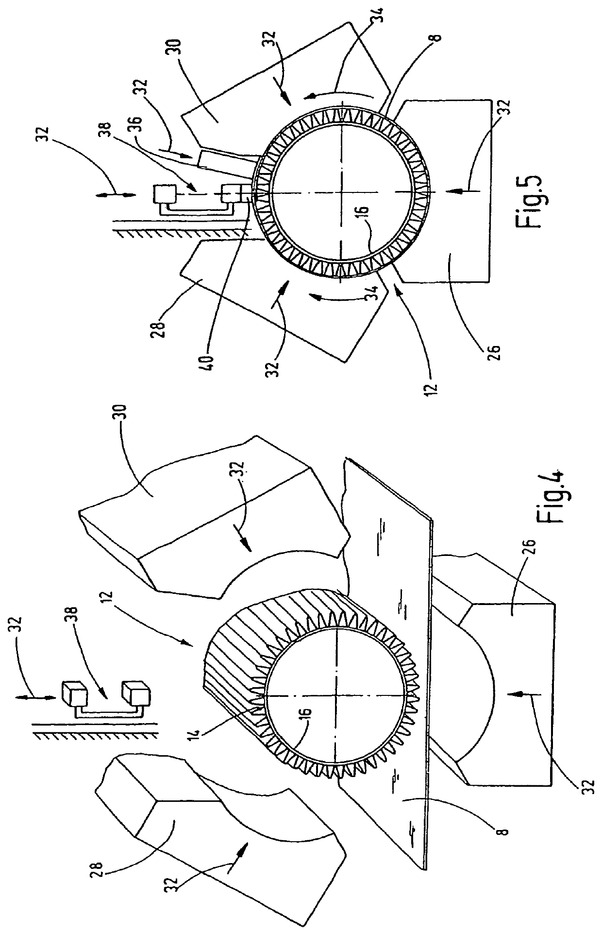
[0022]FIGS. 4 and 5 are in each instance a highly simplified view in schematic form of a processing system for carrying out the method according to the invention. As clear from FIG. 4, the film we...


PUM

PropertyMeasurementUnit
areaaaaaaaaaaa
tensile stressaaaaaaaaaa
areasaaaaaaaaaa

Abstract

A method for producing a filter element for filtering fluids, such as hydraulic fluids, lubricants or fuels, includes the following steps: a) providing at least one section of a filter mat web (14) made of one or more layers of at least one filter medium; b) connecting the ends of the at least one section to form an annular body (12) and placing that annular body onto a support pipe (16); c) wrapping at least one cutout of a film web (8) around the outside of the annular body (12) located on the support pipe (16) and d) placing end areas (24) of the at least one cutout of the film web (8) one on top of the other and connecting the overlapping end areas (24).

Description

FIELD OF THE INVENTION[0001]The invention relates to a method for producing a filter element for filtering fluids, such as hydraulic fluids, lubricants, or fuels. The method comprises the steps of: providing at least one section of a filter mat web made of one or more layers of at least one filter medium; connecting the ends of the at least one section to form an annular body; and placing the annular body onto a support tube.BACKGROUND OF THE INVENTION[0002]Filter elements used in industrial systems to remove the impurities from fluids that are used in the ongoing operations are known from a number of prior art embodiments. For example, EP 1 015 095 B1 shows an advantageous design that has become very popular and is used extensively in pertinent systems. If in operation the filter mat becomes completely clogged with impurities, the filter element has to be changed for a new and unconsumed filter element. In light of the extensive use of such filter elements, having a large quantity ...

Claims


Application Information

Patent Timeline
Patent Type & Authority Patents(United States)
IPC IPC(8): B01D29/31B01D29/21B01D46/00B23K26/20B29C63/06B01D46/24B01D29/11B29C65/00B29C53/38B29C65/50B29C65/16B29C65/48B29C65/08B29L31/14
CPCB01D46/0001B01D29/21B01D46/2411B01D29/111B29C63/06B29C53/38B29C66/1122B29L2031/14B29C66/4322B29C65/168B29C65/4815B29C65/5057B29C65/16B29C65/08
Inventor MEES, HARALD
Owner HYDAC FILTERTECHNIK GMBH
Why Eureka
Try Eureka