Filter assembly

Inactive Publication Date: 2007-02-13
NV BEKAERT SA
View PDF8 Cites 4 Cited by
  • Summary
  • Abstract
  • Description
  • Claims
  • Application Information

AI Technical Summary

Benefits of technology

[0009]It is an object of the present invention to provide a filter assembly holding a filter medium provided with means to disinfect the filter medium. It is a further object to provide a method of disinfecting a filter medium in an efficient and economical way.
[0033]In a preferred method the water and radical pressure is obtained by eliminating, before the heating, all or substantially all the air and the free space around and in the filter medium in order to allow the water and the radicals absorbed and / or formed in a natural way at the surface and / or in the porous structure of the filter medium to be sufficiently numerous to obtain a saturated or substantially saturated water vapour pressure during the heating of the filter medium.
[0036]It is known that all materials in atmospheric conditions absorb a small quantity of water on their surface and that this water presents itself partly under a radical form due to the interaction with the material. Materials made of metal, such as the filter medium comprising metal fibers absorb water and radicals easily.
[0044]eliminating all or substantially all the air and free space around and in the filter medium;
[0047]The air and free space around and in the filter medium is eliminated by reducing the volume of one or more receptacles holding the filter medium. This can be realised by placing the deformable walls of the receptacle against the upper and lower face of the filter medium.
[0050]The presence of a light vacuum is helping to reach a saturated or substantially saturated vapour pressure during the subsequent heating more easily.

Problems solved by technology

Recent studies have indicated that indoor air pollution may pose a great health risk.
Indoor air pollution is in most cases caused by the presence of unwanted particulates, unwanted chemical substances and / or unwanted microorganisms.
The contamination by microorganisms creates a more serious obstacle.
Already after a few hours of operating the filter is contaminated with microorganisms.
However, this technique is only suitable for surface filtration.

Method used


Image

  • Filter assembly
  • Filter assembly

Examples


Embodiment Construction

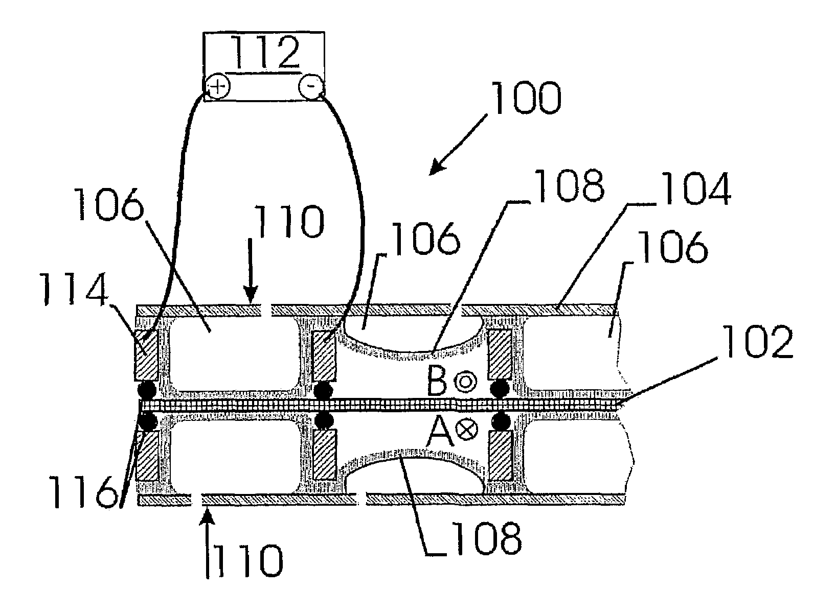
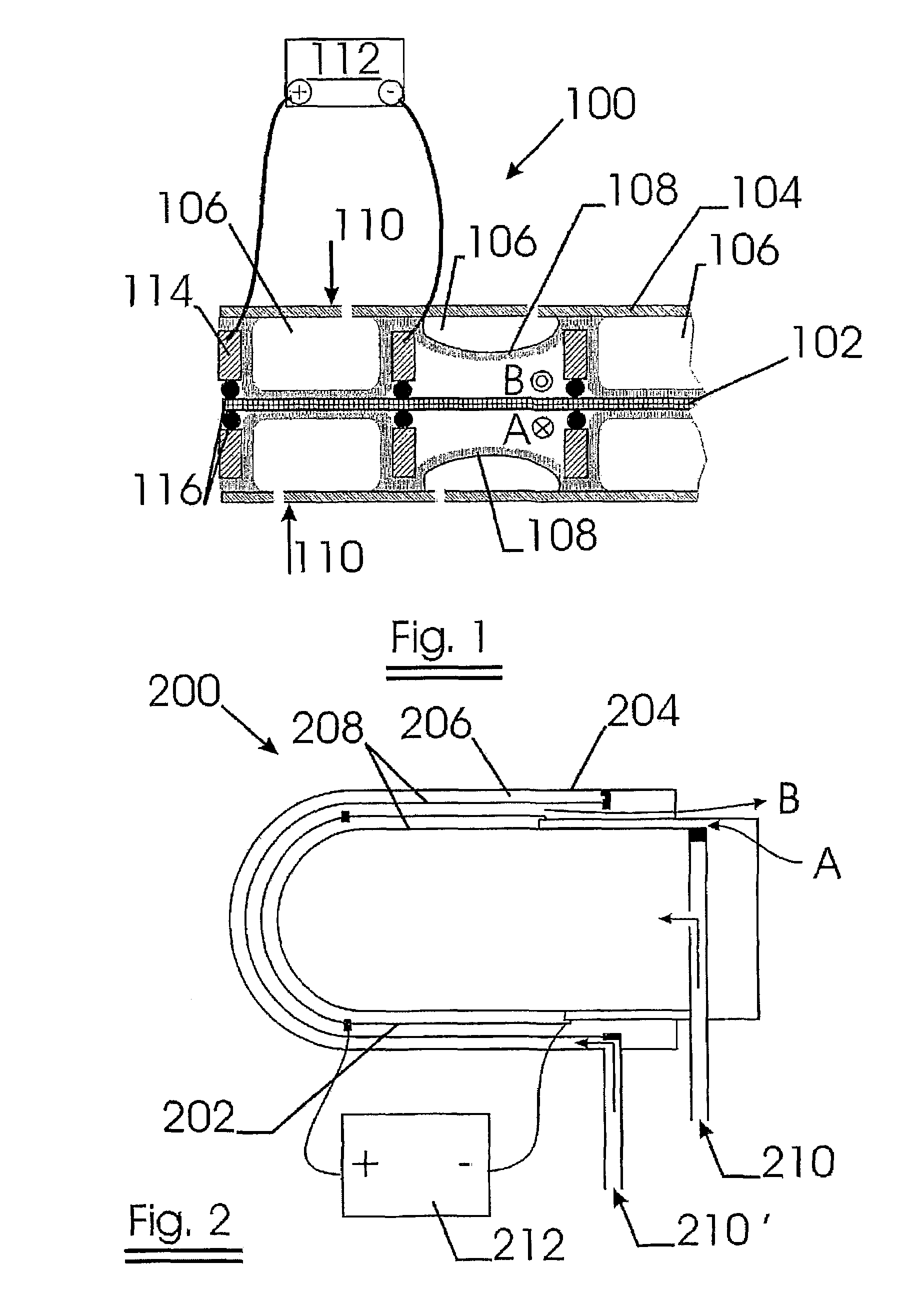
[0056]Referring to FIG. 1, the filter assembly 100 comprises a filter medium 102 and a filter box 104.

[0057]The filter medium comprises a sintered, non-woven metal fiber web. The metal fibers are stainless steel fibers having a diameter of 1.5 μm. The filter rating of the filter medium in air is 0.3 μm.

[0058]The filter box is divided in a number of compartments or receptacles 106, placed next two each other.

[0059]Each of the compartments can be sealed in an airtight manner for example by means of spacing rings 114 and gaskets 116. This allows it to keep one or more compartments impermeable for the air flow to be filtered while the other compartments are still functioning as filter units.

[0060]Each receptacle 106 comprises at least one air inlet, at least one air outlet and two membranes 108 made of a fluoroelastomer VITON®). During a normal filtration regime, the membranes are loose and the air to be filtered passes from face A to face B.

[0061]During a normal filtration regime, the ...


PUM

PropertyMeasurementUnit
Temperatureaaaaaaaaaa
Lengthaaaaaaaaaa
Fractionaaaaaaaaaa

Abstract

A filter assembly including a filter medium installed in at least one receptacle. The filter assembly includes a heating system to heat the filter medium. The filter medium includes metal fibers. The receptacle or receptacles are provided with at least one air inlet and with at least one air outlet and a device to eliminate the air and free space around and in the filter medium. The receptacles may include at least two deformable walls, which are membranes made of a polymeric or elastomeric material, and the filter medium may include at least one sintered, non-woven metal fiber web.

Description

FIELD OF THE INVENTION[0001]The invention relates to a filter assembly holding a filter medium provided with means to disinfect the filter medium. The invention further relates to a method to disinfect a filter medium.BACKGROUND OF THE INVENTION[0002]It is well-known that airborne microorganisms like germs, viruses, fungi and bacteria may cause diseases. Recent studies have indicated that indoor air pollution may pose a great health risk. Indoor air pollution is in most cases caused by the presence of unwanted particulates, unwanted chemical substances and / or unwanted microorganisms.[0003]Unwanted particulates and unwanted chemical substances can in most cases be avoided by conventional techniques such as filtration and ventilation. The contamination by microorganisms creates a more serious obstacle.[0004]HEPA (High Efficiency Particulate Arresting filters) can be used to filter the incoming air by retaining unwanted particulates and unwanted microorganisms such as bacteria.[0005]Ho...

Claims


Application Information

Patent Timeline
IPC IPC(8): B01D35/06A61L2/03A61L2/04A61L2/06A61L2/07A61L2/20A61L2/26A61L11/00B01D39/20B01D46/00B01D46/04B01D46/10B01D46/24
CPCA61L2/03A61L2/04A61L2/07A61L11/00B01D46/10B01D46/0004Y10S55/29B01D2271/027B01D2279/65
Inventor AUBERT, BRUNO
Owner NV BEKAERT SA
Why Eureka
Try Eureka