Light string and manufacturing method thereof

a technology of light strings and manufacturing methods, applied in the field of decorative light strings, can solve the problems of low production efficiency, difficult automatic production, and high cos

Active Publication Date: 2020-05-05
GANZHOU SHANGJIE TECH CO LTD
View PDF5 Cites 2 Cited by
  • Summary
  • Abstract
  • Description
  • Claims
  • Application Information

AI Technical Summary

Benefits of technology

[0002]Light strings are widely applied in various lighting decoration occasions, such as Christmas trees, squares, trees, etc. If color flicker is expected to be realized on the existing light string, a control chip is generally provided for each light source, and then the light source is performed with functional control by technologies of two power lines plus one control line or two power line carrier. The light source is generally formed as a bulb or an independent light bead. When the wires are connected with the light sources, the wires are required to be cut into segments connected between every two light bulbs or light heads, which has high cost, low production efficiency, and is not easy for automatic production.

Problems solved by technology

When the wires are connected with the light sources, the wires are required to be cut into segments connected between every two light bulbs or light heads, which has high cost, low production efficiency, and is not easy for automatic production.

Method used


Image

  • Light string and manufacturing method thereof
  • Light string and manufacturing method thereof
  • Light string and manufacturing method thereof

Examples


first embodiment

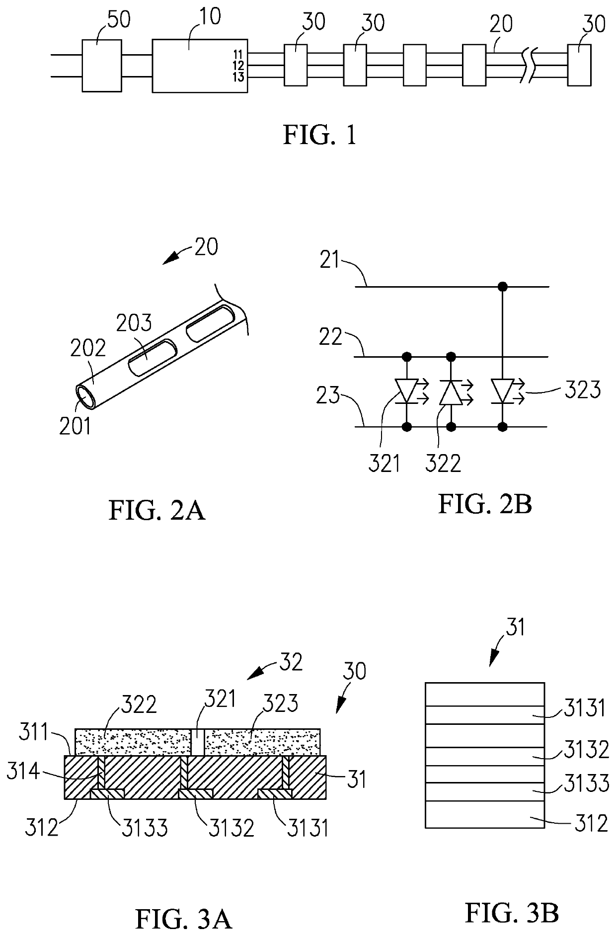
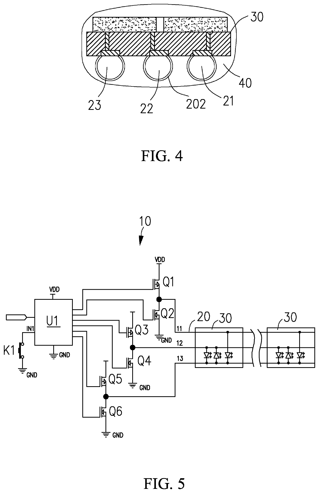
[0015]As shown in FIGS. 1 to 3, in accordance to a first embodiment, a light string of the present invention mainly includes a controller 10, three enameled conductor wires 20 electrically connected to an output terminal of the controller 10, and a plurality of light sources 30 electrically connected to the enameled conductor wires 20 and spaced apart. An input terminal of the controller 10 may be electrically connected to a power adapter 50 to provide a stable power supply voltage for the controller 10, and the power adapter 50 may be matched with a mains socket or other powder socket by a plug or a two-wire plug.

[0016]The conductor wires 20 may be copper wires, aluminium wires, nickel wires, or other available enameled wires, in the embodiment, they are copper wires 201. Each copper wire 201 is covered with an insulating coating 202, in the embodiment, insulated only with varnish to form the insulating coating. The insulating coating 202 on each conductor wire defines many holes 2...

fifth embodiment

[0032]Referring to FIG. 9, in a fifth embodiment, the light string mainly includes a controller 10, two enameled conductor wires 20 electrically connected to the output pins 11, 12 of the controller 10, and a plurality of light sources 30′. Each light sources 30′ includes a circuit board and one or two LEDs connected to the circuit board. The circuit board is a printed circuit board (PCB) having a first surface used for fixing the one or two LEDs and a second surface opposite to the first surface. The second surface includes two conductive strips across the second surface. The two conductive strips are physically and electrically non-connected, and are respectively soldered and electrically connected to the two enameled conductor wires, respectively. The one or two LEDs are electrically connected to the two enameled conductor wires via the two conductive strips of the circuit board. By properly arranging the light sources, various lighting modes may be realized.

[0033]In other embodi...


PUM

PropertyMeasurementUnit
voltageaaaaaaaaaa
voltageaaaaaaaaaa
conductiveaaaaaaaaaa

Abstract

A light string includes at least two conductor wires each covered with an insulating coating defining plural holes acting as electrical bare spots, a controller with an input terminal connected to an external power supply and an output terminal electrically connected to the at least two conductor wires, and plural light sources. Each light source includes one or more LEDs and a circuit board having a first surface used for fixing the one or more LEDs and a second surface defining at least two conductive strips across the second surface. The at least two conductive strips are electrically connected to the at least two conductor wires through the electrical bare spots, respectively. Each connecting part between the conductive strips and the conductor wires is wrapped around by a light transmissive glue. Two conductive ends of each LED are electrically connected to two of the at least two conductive strips.

Description

BACKGROUND OF THE INVENTION1. Field of the Invention[0001]The present invention relates to decorative light strings, and more particularly to a light string and its manufacturing method.2. Description of Related Art[0002]Light strings are widely applied in various lighting decoration occasions, such as Christmas trees, squares, trees, etc. If color flicker is expected to be realized on the existing light string, a control chip is generally provided for each light source, and then the light source is performed with functional control by technologies of two power lines plus one control line or two power line carrier. The light source is generally formed as a bulb or an independent light bead. When the wires are connected with the light sources, the wires are required to be cut into segments connected between every two light bulbs or light heads, which has high cost, low production efficiency, and is not easy for automatic production.BRIEF DESCRIPTION OF THE SEVERAL VIEWS OF THE DRAWIN...

Claims


Application Information

Patent Timeline
Patent Type & Authority Patents(United States)
IPC IPC(8): F21S4/00F21V23/00F21S4/10F21V23/02F21V23/06F21V19/00F21Y103/10F21Y113/13F21Y115/10H05B44/00
CPCF21V23/002F21V23/06F21V19/003F21S4/10F21V23/023F21Y2115/10F21Y2103/10F21Y2113/13F21K9/90F21S10/023F21S10/06F21V19/001F21V23/003F21V23/0407H05B45/00
Inventor ZHU, JIANJUN
Owner GANZHOU SHANGJIE TECH CO LTD
Why Eureka
Try Eureka