
Measurement device for machining center

a measurement device and machining center technology, applied in the field of machining centers, can solve the problems of utilizing additional operator time and slowing down the time to produce components

Active Publication Date: 2020-05-19
FARO TECH INC
View PDF39 Cites 0 Cited by
  • Summary
  • Abstract
  • Description
  • Claims
  • Application Information

AI Technical Summary

Benefits of technology

Enables continuous operation of CNC machining centers with automated, non-contact inspection of workpieces, reducing production time and operator intervention by registering 3D measurements directly within the machining center, thus improving efficiency and accuracy.

Problems solved by technology

Thus the inspection still slows the time to produce components and utilizes additional operator time.

Method used


Image

  • Measurement device for machining center
  • Measurement device for machining center
  • Measurement device for machining center

Examples


Embodiment Construction

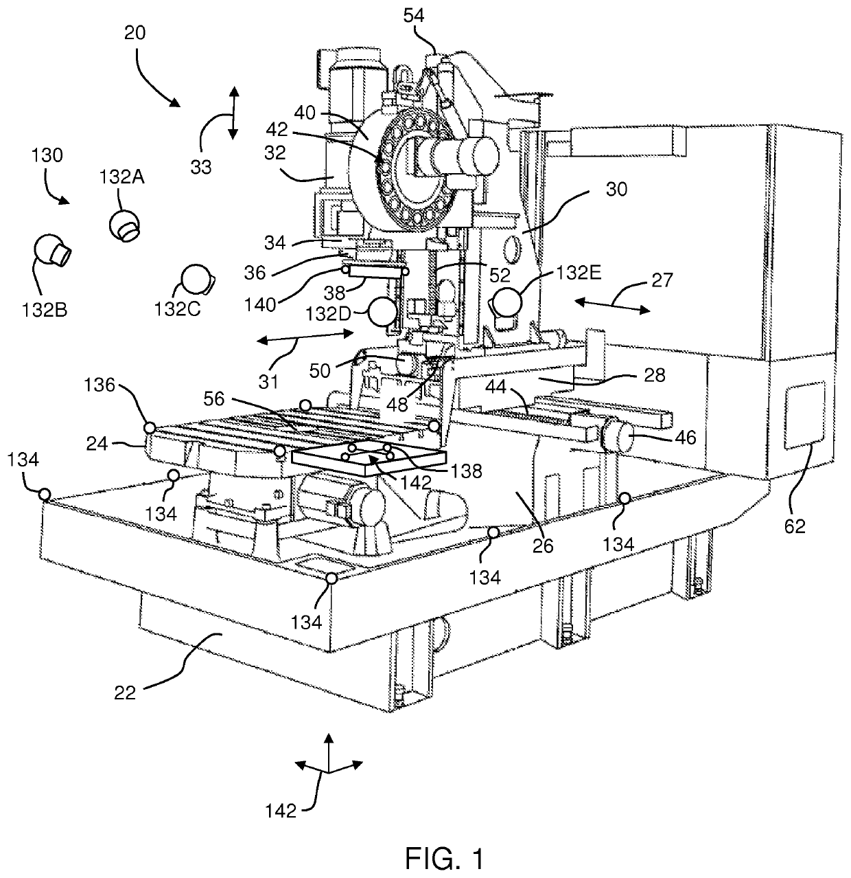
[0018]Embodiments of the present invention provide advantages in allowing for the inspection of work pieces being machined within a CNC machining center without having to remove the work piece. Embodiments of the present invention provide advantages in allowing the inspection of the work piece in an automated manner without interruption by the machine operator. Still further embodiments of the invention provide a noncontact measurement device that may be stored and removed from the machining center tool magazine during operation. Still further embodiments of the invention provide advantages in automating the registration of three-dimensional (3D) measurements using photogrammetry techniques.

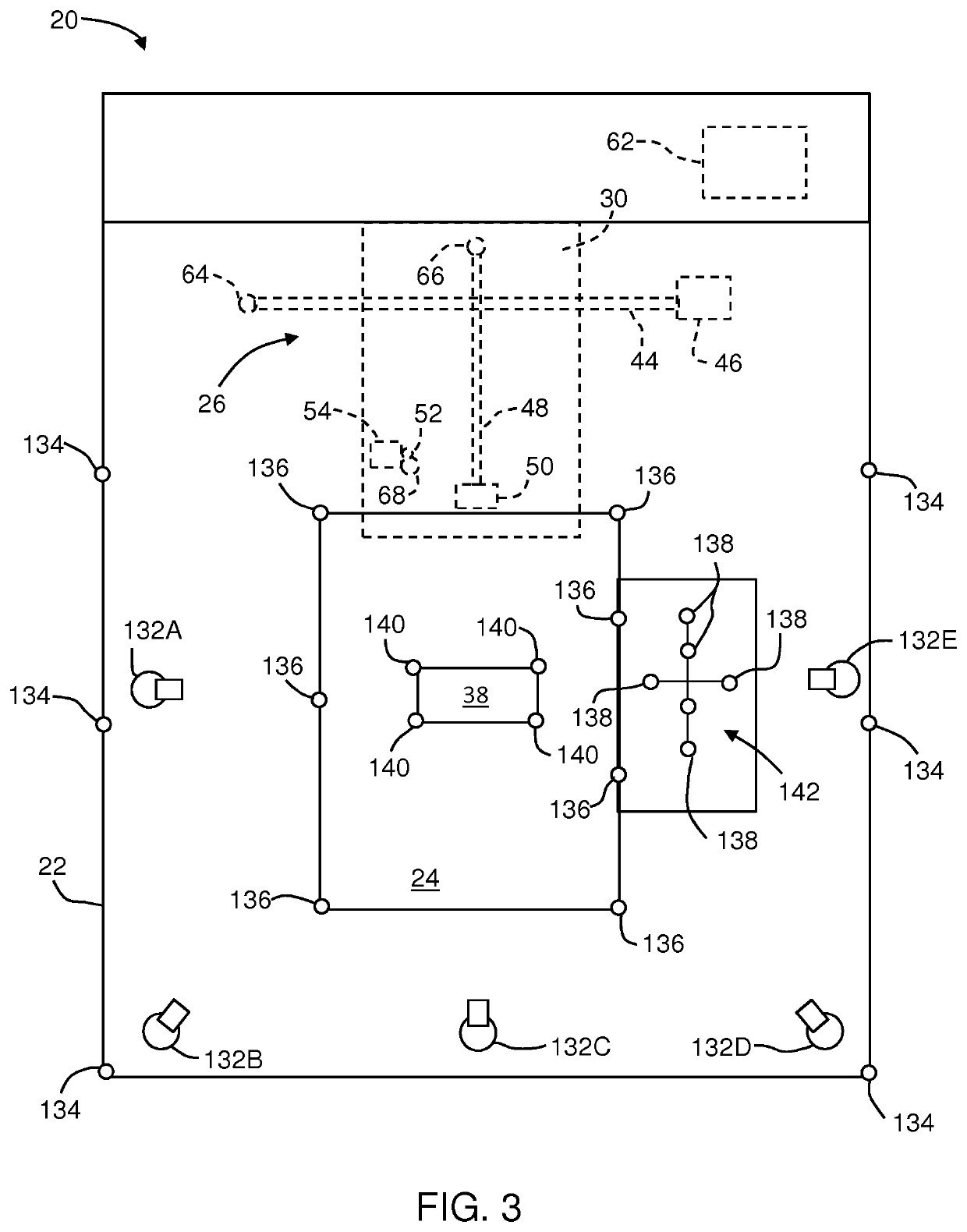
[0019]Referring now to FIGS. 1-3, a CNC machining center 20 is shown in accordance with an embodiment of the invention. The machining center 20 includes a base 22 with a rotatable work table 24 located on one end of the base 22. A sliding rail unit 26 is disposed on an opposite end of the base 22...


PUM


Abstract

A computer numerical control (CNC) machining center is provided. The CNC machining center includes a spindle that receives a cutting tool. A work surface is operably arranged adjacent the spindle. A non-contact three-dimensional (3D) measurement device is operably coupled to the tool mount, the 3D measurement device including a projector and at least one device camera, the at least one camera being arranged to receive light from the light source that is reflected off of a surface. A plurality of targets is provided with at least one of the targets coupled to the 3D measurement device. At least two photogrammetry cameras are provided having a orientation and a field of view to acquire images of the targets. A controller is coupled for communication to the 3D measurement device and the at least two cameras, the controller determining the position of the 3D measurement device within the machining center during operation.

Description

CROSS-REFERENCE TO RELATED APPLICATIONS[0001]The present application is a continuation-in-part of U.S. patent application Ser. No. 14 / 728,014, filed Jun. 2, 2015, which the benefit of U.S. Provisional Patent Application No. 62 / 025,205, filed Jul. 16, 2014, both of which are incorporated herein by reference. The present application also claims the benefit of U.S. Provisional Application No. 62 / 085,746, filed Dec. 1, 2014, which is incorporated by reference herein. The present application also claims the benefit of International Patent Application PCT / US2015 / 033883, filed Jun. 3, 2015, which is incorporated by reference herein.BACKGROUND OF THE INVENTION[0002]The subject matter disclosed herein relates to a machining center and in particular to a machining center having an integrated noncontact measurement device and a photogrammetry system that registers the three-dimensional (3D) measurements into a common frame of reference.[0003]A computer controlled machining center, such as a co...

Claims


Application Information

Patent Timeline
Patent Type & Authority Patents(United States)
IPC IPC(8): G05B19/402B23Q17/24G01C11/02B23Q3/155G01B11/25
CPCB23Q17/249G05B19/402G01B11/2513G01C11/02G01B11/2545B23Q3/155B23Q17/2471G01B2210/58G05B2219/37115Y10T483/17B23Q2230/002
Inventor PFEFFER, CHARLESGRAU, MARKUS
Owner FARO TECH INC
Features
  • Generate Ideas
  • Intellectual Property
  • Life Sciences
  • Materials
  • Tech Scout
  • Unparalleled Data Quality
  • Higher Quality Content
  • 60% Fewer Hallucinations
Learn More