Supercharge Your Innovation With Domain-Expert AI Agents!

Image forming apparatus and fan operation controlling method

a technology of image forming apparatus and fan, which is applied in the direction of cooling/ventilation/heating modification, instruments, printing, etc., can solve the problems of reducing the temperature inside the image forming apparatus, reducing the noise of the exhaust fan, and reducing the air flow

Active Publication Date: 2020-05-26
CANON KK
View PDF3 Cites 4 Cited by
  • Summary
  • Abstract
  • Description
  • Claims
  • Application Information

AI Technical Summary

Benefits of technology

The present patent relates to an image forming apparatus that includes a fan to exhaust air inside the apparatus. The apparatus also includes a controller to control the rotation of the fan. The controller has two control settings for the fan: a first setting and a second setting. The first setting allows the fan to rotate at a predetermined speed to prevent excessive heat and noise while still allowing the image forming unit to form an image. The second setting allows for faster fan rotation to reduce the amount of fine particles released from the apparatus. The apparatus also includes a storage to pre-set the first control setting value for the fan.

Problems solved by technology

However, when air is exhausted through the filter, a loss of air flow occurs, and an effect of suppressing an increase in temperature inside the image forming apparatus is lowered.
However, as the rotation speed increases, the exhaust fan emits louder noise due to wind noise generated by itself and acoustic echo inside a duct.
In this case, there is a possibility that the rotation speed may exceed the target control range during a speed stabilizing time period after the exhaust fan starts to rotate until becoming stable and during a period after the feedback control is started until the rotation speed is controlled to fall within the target control range.
However, when the exhaust fan or the power supply unit is replaced due to, for example, a failure, the variation factor of the rotation speed changes.
In this case, there is a possibility that, with content stored in the nonvolatile memory, it may become unable to control the rotation speed of the exhaust fan to fall within the target control range.
However, work of this processing requires the speed stabilizing time period.
This increases a time period required for replacement and adjustment performed after shipment.
There is also a possibility that the image forming apparatus may unintentionally discharge UFPs when an operation for image forming processing is started before the rotation speed of the exhaust fan reaches the target rotation speed.
For that reason, when the image formation is performed on condition that the rotation speed of the exhaust fan has been controlled to fall within the target control range by the feedback control, a large amount of time is required until the first printed product is output.

Method used


Image

  • Image forming apparatus and fan operation controlling method
  • Image forming apparatus and fan operation controlling method
  • Image forming apparatus and fan operation controlling method

Examples


Embodiment Construction

[0022]An image forming apparatus according to an embodiment of the present disclosure is described with reference to the accompanying drawings.

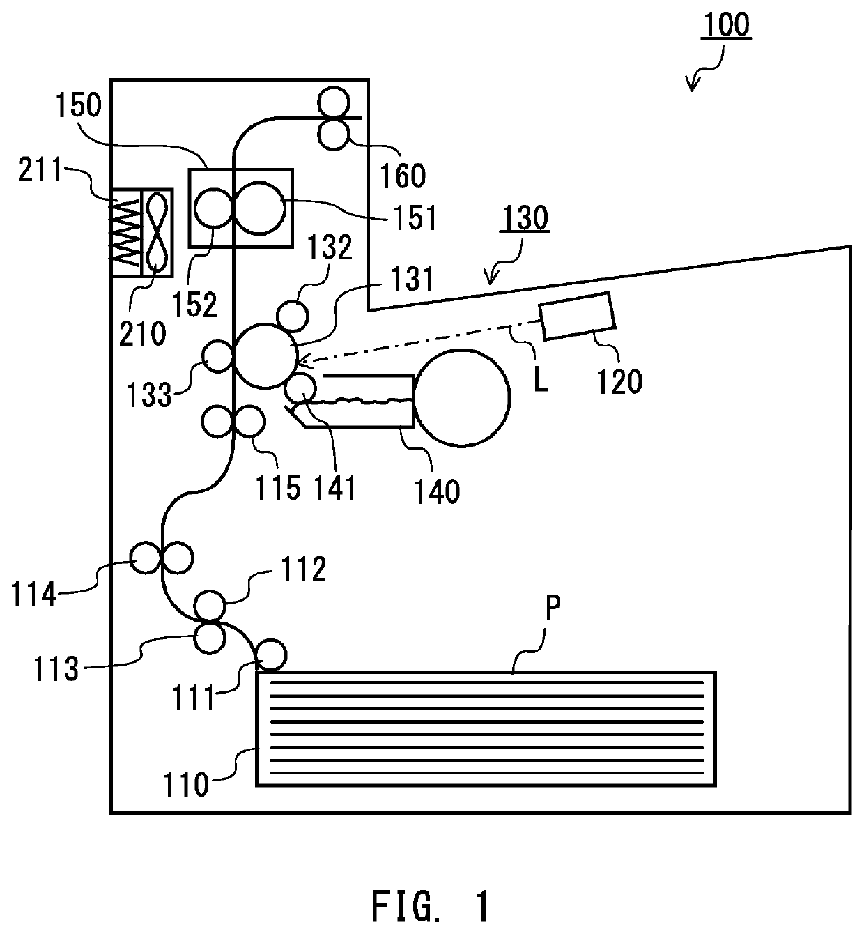
[0023]FIG. 1 is a configuration diagram of a printer serving as an image forming apparatus according to this embodiment. A printer 100 includes a sheet feeding cassette 110 capable of receiving a plurality of recording materials (or sheets of recording paper) P, for example, sheets, a conveyance path for conveying the recording material P, an image forming unit 130 configured to form an image on the recording material P, a fixing device 150, and an exhaust fan 210 for suppressing an increase in temperature inside the printer 100. In order to feed the recording material P, the conveyance path includes a pickup roller 111, a sheet feeding roller 112, a retard roller 113, a conveyance roller pair 114, a registration roller pair 115, and a discharge roller pair 160. The image forming unit 130 includes a photosensitive drum 131, a charging roller ...


PUM


Abstract

Provided is an image forming apparatus including: an image forming unit configured to form an image on a recording material; an exhaust fan configured to exhaust air inside the image forming apparatus; a CPU configured to control rotation of the exhaust fan; and a memory configured to store in advance a first control setting value for rotating the exhaust fan at a first target rotation speed. The CPU rotates the exhaust fan based on the first control setting value, and permits the image forming unit to form an image when a rotation speed of the exhaust fan becomes equal to or faster than a lower limit rotation speed for suppressing a discharge amount of UFPs. When a predetermined time period has elapsed, the CPU performs feedback control for the exhaust fan such that the exhaust fan is rotated faster than the first target rotation speed.

Description

BACKGROUND OF THE INVENTION[0001]Field of the Invention[0002]The present disclosure relates to an image forming apparatus, for example, a copying machine, a printer, or a facsimile machine, and more particularly, to control of a fan motor provided inside an image forming apparatus.[0003]Description of the Related Art[0004]An image forming apparatus includes an exhaust fan motor (hereinafter referred to as “exhaust fan”) for suppressing an increase in temperature inside the image forming apparatus. The exhaust fan exhausts heated air inside the image forming apparatus. At a time of exhausting air, fine particles and the like may be discharged along with air. Such fine particles and the like are required to be reduced from the viewpoint of environmental protection. For example, in “Blue Angel”, German certification for products and services, a discharge amount of ultra-fine particles (UFPs), which are ultra-fine particles discharged from a product, is regulated. Therefore, the image f...

Claims


Application Information

Patent Timeline
Patent Type & Authority Patents(United States)
IPC IPC(8): G03G21/20H05K7/20
CPCG03G21/206H05K7/20172H05K7/20209B41J29/377
Inventor FUNABA, HIROSHI
Owner CANON KK
Features
  • R&D
  • Intellectual Property
  • Life Sciences
  • Materials
  • Tech Scout
  • Unparalleled Data Quality
  • Higher Quality Content
  • 60% Fewer Hallucinations
Learn More