
Ear instrument assembly

a technology of ear instruments and parts, applied in the field of ear instruments, can solve the problems of difficult visualization, bulky and difficult maneuverability, and the difficulty of viewing into the ear of a child,

Active Publication Date: 2020-06-02
WUJCIAK ANNA J
View PDF28 Cites 0 Cited by
  • Summary
  • Abstract
  • Description
  • Claims
  • Application Information

AI Technical Summary

Benefits of technology

[0001]During diagnosis of ear maladies and cerumen removal, it is desirable that a physician is able to visualize various regions of the ear such as the tympanic membrane. The size and shape of the ear canal, the patient's sensitivity, as well as the presence of cerumen, can make visualization difficult. An otoscope is used to gain a better view of the ear canal, cerumen, and tympanic membrane. However, otoscopes are often held similar to a hammer which can be bulky and challenging to maneuver. Otoscopes can block quite a bit of space at the opening of the ear canal, which can make viewing into a child's ear more challenging because a child's ear is smaller, children tend to move more, and an otoscope can be a frightening object to a child. Therefore, additional time is usually required trying to calm and / or secure the position of the child patient to view the ear canal or tympanic membrane.

Problems solved by technology

The size and shape of the ear canal, the patient's sensitivity, as well as the presence of cerumen, can make visualization difficult.
However, otoscopes are often held similar to a hammer which can be bulky and challenging to maneuver.
Otoscopes can block quite a bit of space at the opening of the ear canal, which can make viewing into a child's ear more challenging because a child's ear is smaller, children tend to move more, and an otoscope can be a frightening object to a child.
Repeating the process to remove cerumen can cause irritation of the tissue inside the channel.

Method used


Image

  • Ear instrument assembly
  • Ear instrument assembly
  • Ear instrument assembly

Examples


Embodiment Construction

[0017]Those having ordinary skill in the art will recognize that all directional references (e.g., above, below, upward, up, downward, down, top, bottom, left, right, vertical, horizontal, etc.) are used descriptively for the FIGS. to aid the reader's understanding, and do not represent limitations (for example, to the position, orientation, or use, etc.) on the scope of the disclosure, as defined by the appended claims. Furthermore, the term “substantially” can refer to a slight imprecision or slight variance of a condition, quantity, value, or dimension, etc., some of which that are within manufacturing variance or tolerance ranges. The phrase “at least one of” as used herein should be construed to include the non-exclusive logical “or”, i.e., A and / or B and so on depending on the number of components.

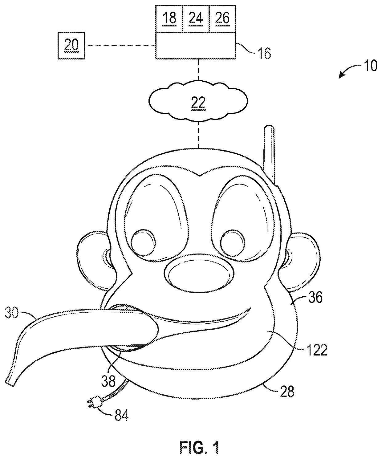
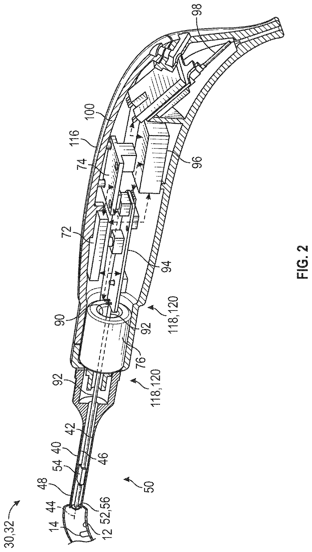
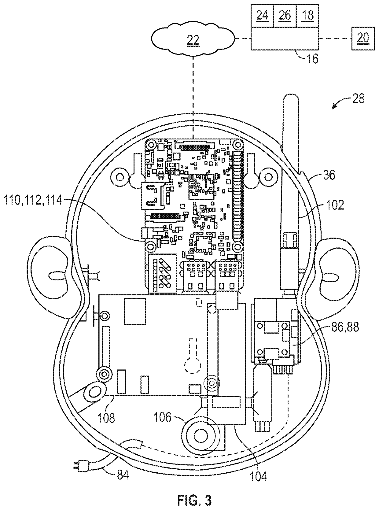
[0018]Referring to the FIGS., wherein like numerals indicate like or corresponding parts throughout the several views, an ear instrument assembly 10 is generally shown in FIG. 1. Gen...


PUM


Abstract

An ear instrument assembly includes a base unit and a tool. The base unit includes a first housing defining an opening. The tool is movable between a storage position in which the tool is partially disposed into the opening such that the tool is secured to the first housing and a use position in which the tool is removed from the opening such that the tool is spaced from the first housing. The tool includes a tip contained inside the first housing when the tool is in the storage position. The tool includes a camera at least partially disposed in the tip of the tool, and the tool includes a curette attachable to and detachable from the tip of the tool.

Description

INTRODUCTION[0001]During diagnosis of ear maladies and cerumen removal, it is desirable that a physician is able to visualize various regions of the ear such as the tympanic membrane. The size and shape of the ear canal, the patient's sensitivity, as well as the presence of cerumen, can make visualization difficult. An otoscope is used to gain a better view of the ear canal, cerumen, and tympanic membrane. However, otoscopes are often held similar to a hammer which can be bulky and challenging to maneuver. Otoscopes can block quite a bit of space at the opening of the ear canal, which can make viewing into a child's ear more challenging because a child's ear is smaller, children tend to move more, and an otoscope can be a frightening object to a child. Therefore, additional time is usually required trying to calm and / or secure the position of the child patient to view the ear canal or tympanic membrane.[0002]Generally, otoscopes are utilized to view inside of the patient's ear, but ...

Claims


Application Information

Patent Timeline
Patent Type & Authority Patents(United States)
IPC IPC(8): A61B1/00A61B1/05A61B1/227A61B1/045A61B1/06
CPCA61B1/045A61B1/0661A61B1/00128A61B1/00011A61B1/227A61B1/051A61B1/00034A61B1/00087A61B1/00101A61B1/00144
Inventor WUJCIAK, ANNA J.WANG, JENNIE C.HUDIK, BRANDON J.JONES, CAROLINE N.
Owner WUJCIAK ANNA J
Learn More