Method and apparatus for correcting motions of robot

a robot and motion correction technology, applied in the direction of programmed manipulators, instruments, programme control, etc., can solve the problems of excessive force and loss of accurate alignment made under control, and achieve high accuracy, high accuracy, and high accuracy

Active Publication Date: 2020-06-02
DENSO WAVE INC
View PDF5 Cites 0 Cited by
  • Summary
  • Abstract
  • Description
  • Claims
  • Application Information

AI Technical Summary

Benefits of technology

[0013]Thus, the mechanical deflection amount of the first axis can be calculated without the need of providing an additional component, such as a force sensor. Then, based on the deflection amount, a control value is corrected for the control of the robot, which eliminates the need of enhancing rigidity of the arm. Accordingly, change in robot motion due to deflection caused in the joint axis of the robot can be corrected without curbing reduction in size or weight or speed increase of the robot.
[0015]In still another example, an angle detected on an output-shaft side of the first axis is corrected based on the deflection amount. Thus, the actual rotation angle of the first axis can be properly acquired in the occurrence of an error in the detected angles due to deflection of the first axis. Accordingly, the rotation angle of the first axis can be correctly controlled and, for example, the distal end position of the tool can be determined with high accuracy.
[0016]Preferably, an estimated load torque to be applied to the first axis may be corrected based on the deflection amount. Thus, the actual load torque can be estimated with high accuracy in the occurrence of an error in the estimation of the load torque due to deflection of the first axis. This way of correction can prevent the workpiece from being damaged due to the robot applying an excessive force thereto as a result of erroneously determining the load torque as being excessively small, or from being erroneously assembled due to the robot being unable to generate a necessary force as a result of erroneously determining the load torque as being excessively large.
[0017]Preferably, a distal end position of a tool may be corrected based on the deflection amount. Thus, in the occurrence of misalignment of the distal end position of the tool due to deflection of the first axis, the misalignment can be corrected. Accordingly, the distal end position of the tool can be determined with high accuracy, which leads to preventing assemblage at an erroneous position, or reducing possible scratches on the surface of the workpiece or possible damage to the workpiece.
[0018]According to still another typical example, a correction apparatus for a robot may include a moment acquisition section acquiring a moment applied to a first axis in a non-rotation direction, a deflection amount acquisition section acquiring a deflection amount of the first axis, and a correction section correcting a control value based on the deflection amount. Thus, as described above, since there is no need of additionally providing a component, such as a force sensor, to the robot, or enhancing rigidity of the arm, deflection occurring in the robot can be corrected without curbing reduction of size or weight or speed increase of the robot. Accordingly, the distal end position of the tool can be determined with high accuracy, and the force applied to the distal end of the tool can be detected with high accuracy. Consequently, the robot is able to conduct work of great difficulty that needs high assembling accuracy.

Problems solved by technology

However, the fact is that accurate alignment made under control may be lost due to mechanical deflection of the robot which is caused by its own weight or the like.
In the occurrence of mechanical deflection, the tip end position of the tool may be misaligned from the target position, disabling assemblage of the workpiece, or the load torque may be erroneously estimated, leading to application of an excessively large force.

Method used


Image

  • Method and apparatus for correcting motions of robot
  • Method and apparatus for correcting motions of robot
  • Method and apparatus for correcting motions of robot

Examples


Embodiment Construction

[0029]With reference to the drawings, various embodiments will be described.

[0030]Referring first to FIGS. 1 to 8, a description will be given of a method and an apparatus for correcting mechanical deflection caused in a robot, according to an embodiment. As will be described later, these method and apparatus are embodied by a controller that controls a robot.

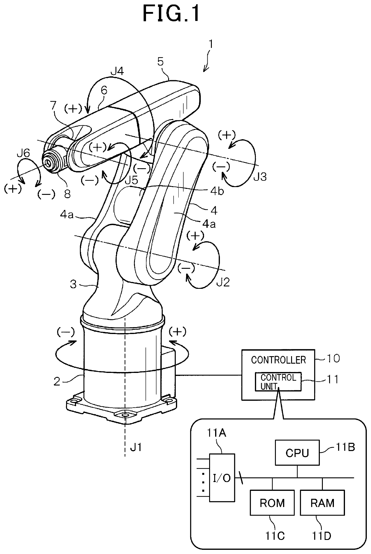
[0031]FIG. 1 is a schematic perspective view illustrating an overall configuration of a robot 1, according to an embodiment of the present disclosure. As shown in FIG. 1, the robot 1 having a known configuration as a vertical articulated robot is connected to a controller 10. The controller 10 serves as a correction apparatus having a correction function unique to the present disclosure.

[0032]The controller 10 is provided with a control unit 11 that includes a microcomputer, not shown. The control unit 11 includes, as an example, an input / output interface 11A, a CPU (central processing unit) 11B, a ROM (read only memory) 11C st...


PUM


Abstract

In an industrial robot, correction is made for change in position and attitude of an arm distal end due to mechanical deflection of the robot. In the robot, a moment applied to the first axis in its non-rotation direction opposite to its rotation direction is calculated from a load torque applied to the second axis in its rotation direction, a moment due to a second-axis-side self-weight, and a ratio of a distance between the rotation centers of the first and second axes, to a distance between the rotation centers of the second axis and a tool. A deflection amount indicating an angle of the first axis tilting in the non-rotation direction is calculated from the moment applied to the first axis and the rigidity of the first axis in the non-rotation direction. A control value is corrected based on the deflection amount to control the robot.

Description

CROSS-REFERENCE TO RELATED APPLICATION[0001]This application is based on and claims the benefit of priority from earlier Japanese Patent Application No. 2016-245489 filed Dec. 19, 2016, the descriptions of which are incorporated herein by reference.BACKGROUND[0002][Technical Field ][0003]The present disclosure relates to a method and apparatus for correcting motions of a robot, and in particular, to a method and apparatus for correcting changes in motions of industrial robots due to mechanical deflection developed in the robot.[0004][Related Art ][0005]Industrial robots nowadays are indispensable production means in factories and other facilities. These industrial robots (simply termed robot(s) hereinafter) are generally used, with a tool suitable for the usage being attached to the end effector. Such a robot may make a motion applying a force in a direction perpendicular to its installation surface, such as when assembling a workpiece held by the tool to a predetermined position of...

Claims


Application Information

Patent Timeline
Patent Type & Authority Patents(United States)
IPC IPC(8): B25J9/16B25J15/00
CPCB25J15/0019B25J9/1641G05B2219/39186Y10S901/41Y10S901/02
Inventor FUKUOKA, TAKAFUMIKAWACHI, YUTOSHIRATORI, HIROAKIKAWASE, DAISUKE
Owner DENSO WAVE INC
Why Eureka
Try Eureka