Dynamic field of view endoscope

a technology of endoscope and dynamic field of view, which is applied in the field of multi-sensor endoscope, can solve the problems of other limitations of the related art, and achieve the effect of reducing the number of endoscopes

Active Publication Date: 2020-06-09
270 SURGICAL LTD
View PDF52 Cites 166 Cited by
  • Summary
  • Abstract
  • Description
  • Claims
  • Application Information

AI Technical Summary

Benefits of technology

[0045]In another embodiment, the present invention provides a method of achieving a dynamic field of view in an endoscope that can alternate its field of view parameters by using at least two sensors, wherein at least one sensor can move in respect to other sensor.

Problems solved by technology

Other limitations of the related art will become apparent to those of skill in the art upon a reading of the specification and a study of the figures.

Method used


Image

  • Dynamic field of view endoscope
  • Dynamic field of view endoscope
  • Dynamic field of view endoscope

Examples


Embodiment Construction

[0055]An aspect of embodiments related to an endoscope having an elongated shaft terminating with a tip section, a maneuvering section and two or more sensors, wherein at least one sensor is placed behind the tip section. Preferably, the sensor is a camera. For simplicity of discussion the sensors are represented by cameras, which are meant to be exemplary and illustrative, not limiting in scope.

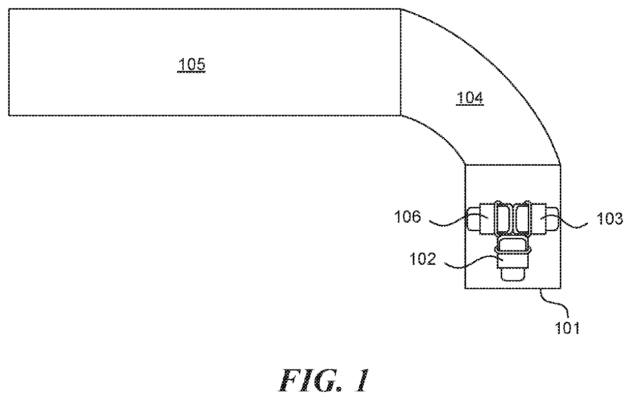
[0056]Reference is now made to FIG. 1, which shows across sectional view of a prior art endoscope, in this example three cameras (102, 103 and 106) (as well as other elements such as a light source or a working channel, not shown) are located at the tip section (101). In this case when the shaft (105) is moving or bended, using bending section (104), the entire tip is moving and as a result the whole sensor's image is moving as well without the option of changing the directions of the cameras relatively to each other. The present invention provides an endoscope having one or more maneuvering...


PUM


Abstract

The subject matter discloses a multi-sensor endoscope having a dynamic field of view comprising an elongated shaft terminating with a tip section; a maneuvering section connected to the elongated shaft; at least two sensors, wherein at least one sensor is placed behind the tip section, on the maneuvering section; and one or more illuminators located on external surface of the shaft. In some cases, the sensors include a camera. The subject matter also discloses a multi-sensor endoscopy system comprising an endoscope comprising a handle and a controller, such that the maneuvering section is controlled by the controller.

Description

CROSS-REFERENCE TO RELATED APPLICATION[0001]This application is a continuation of International Application No. PCT / IL2016 / 050515 with an international filing date of May 15, 2016, which claims priority to U.S. Provisional Patent Application No. 62 / 160,253 filed May 12, 2015, the entire contents of each of which are incorporated herein by reference.FIELD OF THE INVENTION[0002]The present specification relates generally to a multi sensor endoscope having a dynamic field of view.BACKGROUND OF THE INVENTION[0003]Endoscopes have attained great acceptance within the medical community, since they provide a means for performing procedures with minimal patient trauma, while enabling the physician to view the internal anatomy of the patient. Over the years, numerous endoscopes have been developed and categorized according to specific applications, such as laparoscopy, hysteroscopy, cystoscopy, colonoscopy, upper GI endoscopy and others. Endoscopes may be inserted into the body's natural orif...

Claims


Application Information

Patent Timeline
Patent Type & Authority Patents(United States)
IPC IPC(8): A61B1/00A61B8/12A61B6/00A61B5/01A61B5/00A61B1/313A61B1/06A61B1/005G02B23/24A61B1/05A61B90/30
CPCA61B1/00114A61B1/3132A61B5/0086A61B1/00183A61B1/00096G02B23/2484A61B6/4057A61B1/0008A61B1/005A61B1/0051A61B1/00045A61B5/0035A61B5/015A61B8/12A61B1/0676A61B1/05A61B1/00181A61B1/00006A61B1/051A61B1/00066A61B2090/309A61B1/0625A61B1/009
Inventor LEVY, AVRAHAM
Owner 270 SURGICAL LTD
Why Eureka
Try Eureka