
Digging bar attachment for toothed bucket

a technology of toothed buckets and attachment devices, which is applied in the direction of mechanical machines/dredgers, soil-shifting machines/dredgers, and construction. it can solve the problems the inability to smooth out the area, and the inability to dig in the area with utility lines hidden beneath the ground level. it can solve the problem of affecting the smoothing effect of the area, and the inability to use the device. the method is simplified

Active Publication Date: 2020-06-23
HARDIN BRANDON
View PDF20 Cites 1 Cited by
  • Summary
  • Abstract
  • Description
  • Claims
  • Application Information

AI Technical Summary

Benefits of technology

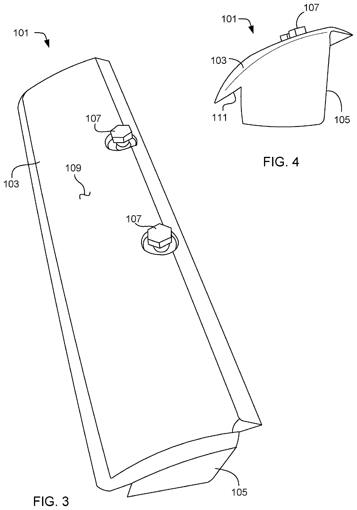
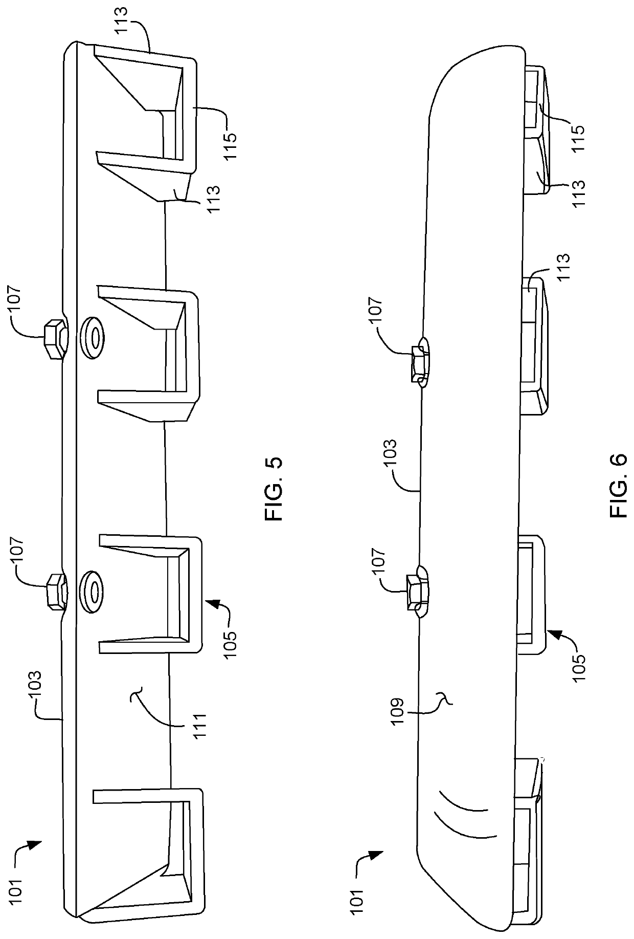
The invention is a device that simplifies the process of tightening teeth fasteners by sliding the device over the teeth and rotating the fasteners into place. This avoids the need for a special bucket or sacrificing the teeth through welding. The device can be used with various embodiments and offers a more efficient and effective solution for tightening teeth fasteners.

Problems solved by technology

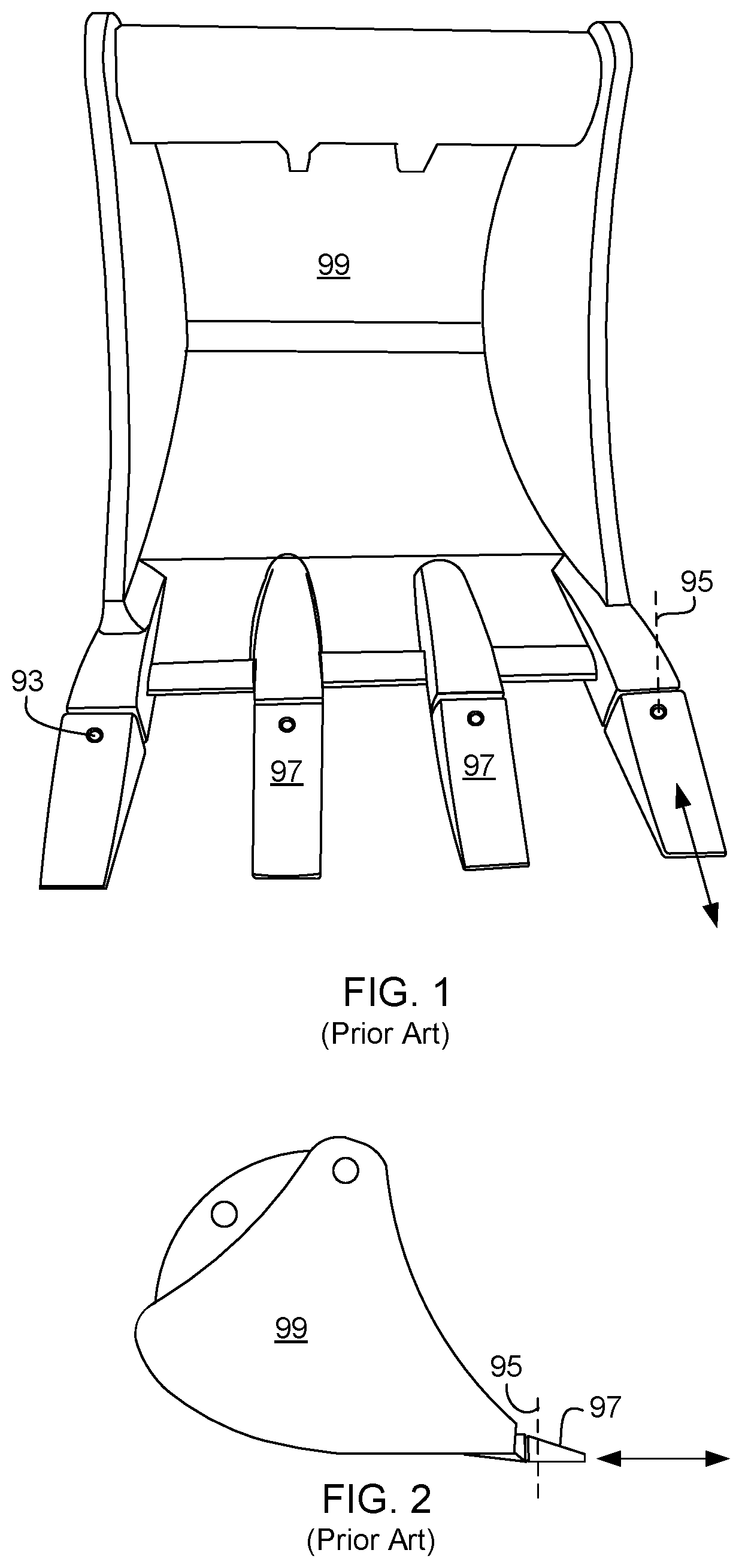
An issue that arises with these buckets is that they include teeth that are adapted nicely for digging without concern for what is underground, but are grossly inadequate for smoothing out an area or for digging in areas with utility lines hidden beneath ground level.
Currently, the issue is with having teeth.
The teeth can catch on underground cables, puncture water lines, along with other types of issues.
Furthermore, the teeth prevent the bucket from being used to smooth out an area of dirt as the teeth are spaced.
Swapping buckets on large machinery is not a simple task and can result in lots of down time for the equipment.
Although a simple plate is smaller than a bucket, downtime is still an issue.
When the tasks are finished, the plate can not be removed without sacrificing the teeth.
Both methods result in lost time and increased costs.
Most solutions complicate the problem by incorporating devices that surround the teeth but also wrap up the sides of bucket 99.
Some designs use fasteners to compress the device onto the teeth but these can lose grip on the teeth and fall off.

Method used


Image

  • Digging bar attachment for toothed bucket
  • Digging bar attachment for toothed bucket
  • Digging bar attachment for toothed bucket

Examples


Embodiment Construction

[0028]Illustrative embodiments of the preferred embodiment are described below. In the interest of clarity, not all features of an actual implementation are described in this specification. It will of course be appreciated that in the development of any such actual embodiment, numerous implementation-specific decisions must be made to achieve the developer's specific goals, such as compliance with system-related and business-related constraints, which will vary from one implementation to another. Moreover, it will be appreciated that such a development effort might be complex and time-consuming but would nevertheless be a routine undertaking for those of ordinary skill in the art having the benefit of this disclosure.

[0029]In the specification, reference may be made to the spatial relationships between various components and to the spatial orientation of various aspects of components as the devices are depicted in the attached drawings. However, as will be recognized by those skille...


PUM


Abstract

A digging attachment device for use with a toothed earth working bucket includes a contoured plate configured to be at least the width of the combined teeth of the bucket and extends over the ends of the teeth when seated. The device further includes a plurality of slots coupled to a lower surface of the plate. The slots are configured to accept the teeth of the bucket. The slots are tapered such that its internal distance within the slots relative to the lower surface of the plate progressively decreases to match the contour of the bucket teeth. The device further includes a fastener hole and fastener in communication with at least one of the plate and slots. The fastener is configured to be set within the countersink of the teeth fasteners. The device is secured without manipulation, adjustment, and removal of any portion of any earth working bucket.

Description

BACKGROUND1. Field of the Invention[0001]The present application relates to an attachment for an excavator bucket, and more particularly to a removable digging bar attachment device for coupling to the teeth of the excavator bucket.2. Description of Related Art[0002]Various types of large machinery use front or rear buckets for moving large amounts of earth at a time. The buckets are coupled to a mechanical arm that typically uses one or more hydraulic systems to actuate the bucket between forward and rearward positions. One type of bucket is shown in FIG. 1 and FIG. 2. The buckets have a relatively deep concave portion for scooping up dirt. A series of teeth 97 are located along a forward bottom surface of the bucket 99. As seen in FIGS. 1 and 2, the teeth are coupled to the bucket with fasteners that pass along axis 95. The fasteners may be a threaded fastener such as a screw. The head of the fasteners include a countersink area. The teeth help to puncture the ground and facilitat...

Claims


Application Information

Patent Timeline
IPC IPC(8): E02F3/96E02F3/40
CPCE02F3/40E02F3/962E02F9/2883
Inventor HARDIN, BRANDON
Owner HARDIN BRANDON
Learn More