
Seal arrangement with damping element

a technology of damping element and sealing arrangement, which is applied in the direction of vibration dampers, mechanical equipment, engine components, etc., can solve problems such as unsuitability for use, and achieve the effect of simplifying installation

Active Publication Date: 2020-06-23
TRELLEBORG SEALING SOLUTIONS GERMANY
View PDF27 Cites 0 Cited by
  • Summary
  • Abstract
  • Description
  • Claims
  • Application Information

AI Technical Summary

Benefits of technology

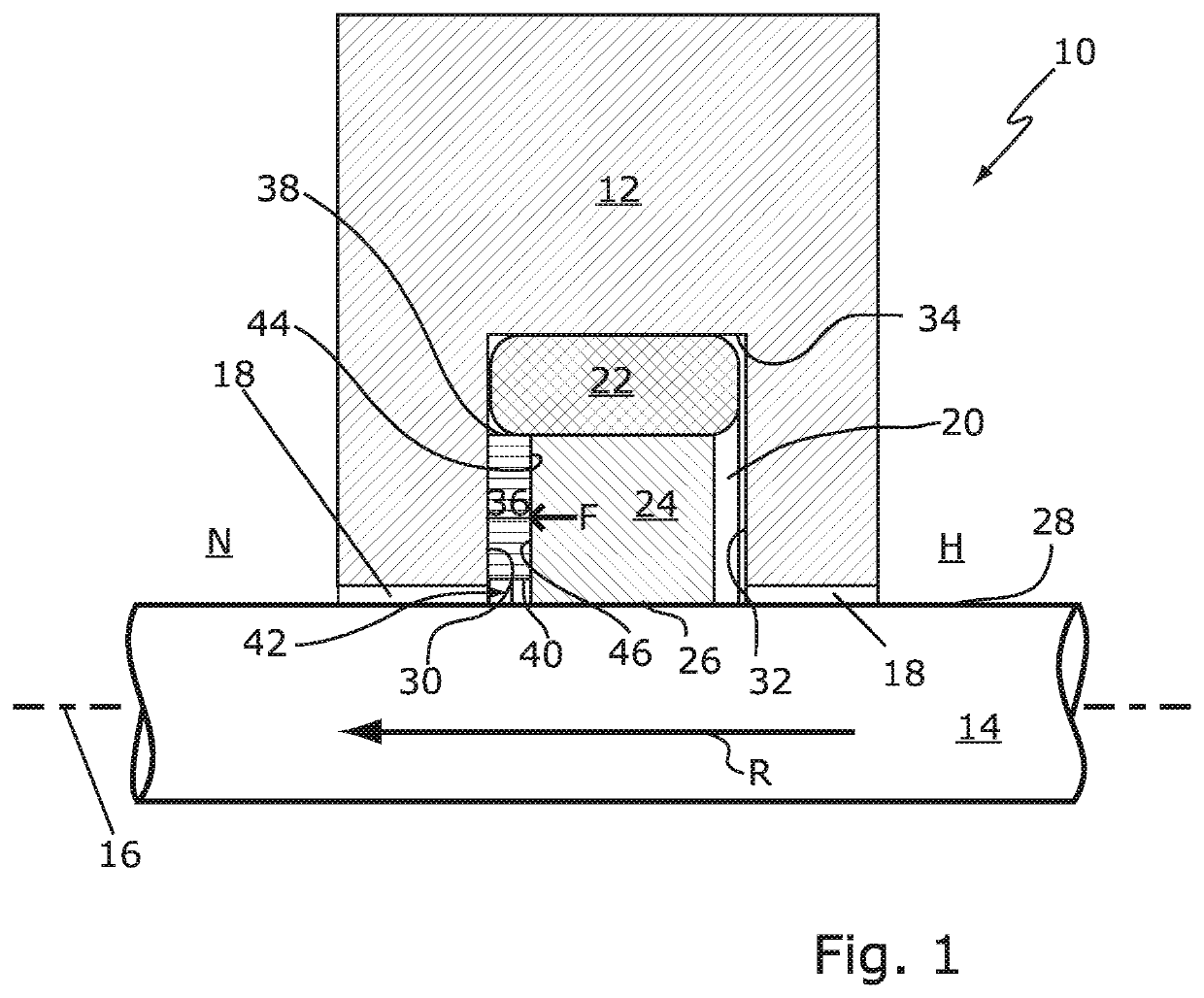
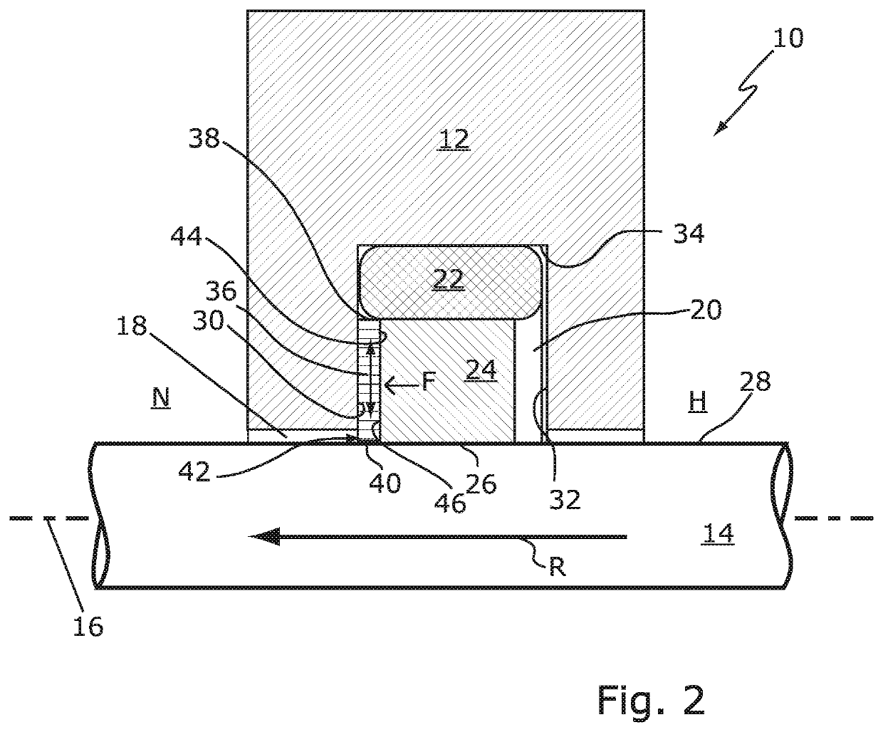
[0010]In the pressurized operating state of the seal arrangement or in the case of an axial movement (concomitant movement), associated with the relative movement of the two machine elements, of the seal element in the direction of the low-pressure side of the seal arrangement, the seal element can be supported on the damping member. Under the axially directed force pressing the seal element against the damping member, the damping member is deformed elastically owing to its lower elasticity modulus in comparison with the material of the seal element. It is thereby possible to reliably counteract overloading and concomitant damage of the seal element, even in the case of high- or ultrahigh-pressure applications or high levels of acceleration of the translational relative movement of the two machine elements. Furthermore, the seal element can be given smaller dimensions overall, i.e. can be embodied with a smaller total volume, than is possible without such a damping member. This is advantageous in respect of the cold shrinkage behavior of the seal element. Moreover, the seal element can be composed of a material that is less resistant to mechanical loads without this having a negative effect on the operating life of the seal element. Thus, the seal element can be manufactured (composed) of a material which, on the one hand, is distinguished by a particularly low friction coefficient but which has hitherto been regarded as unsuitable for use in a seal arrangement mentioned at the outset owing to its low resistance to static / dynamic operational loads. Here, the reduced friction coefficient allows lower wear and an even broader technical range of applications of the seal arrangement. The damping member furthermore makes it possible to counteract possible unwanted vibrations in the seal arrangement caused by the stick-slip effect (stick-slip behavior) of the seal element resting on the sealing surface of the second machine part.
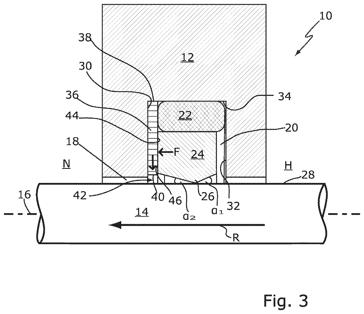
[0011]A free space is formed between the damping member and the sealing surface of the second machine part, into which space the damping member can be deformed elastically in the direction of the second machine element when subjected to the contact pressure force of the seal element, which is directed axially in the direction of the low-pressure side. Said free space thus ensures that the damping member can expand freely transversely to the movement axis. The free space is delimited in the radial direction by the sealing surface of the second machine element and an inner wall, facing the sealing surface, of the damping member. In other words, the free space extends continuously from the inner wall of the damping member to the sealing surface of the second machine element. The term “free space” is taken to mean a spatial volume of the seal arrangement in which no solid body, i.e. no component of the seal arrangement, is arranged. Overall, the deformation space required for the damping effect of the damping member is thereby made available. Moreover, it is thereby possible to enlarge an effective supporting surface of the damping member for the seal element in proportion to the contact pressure force of the seal element against the damping member, i.e. in proportion to an atmospheric pressure prevailing in the high-pressure region of the seal arrangement.
[0012]Even better protection of the seal element from overloading or damage is achieved according to the invention by virtue of the fact that the damping member partially covers the sealing gap in the axial direction, at least in the pressurized state of the seal arrangement (or of the high-pressure region). In this case, the damping member has the additional function of a barrier element, by means of which the clear width of the sealing gap can be partially shifted dynamically, i.e. in accordance with the contact pressure force acting on the damping member. It is thereby possible reliably to counteract the risk of plastic deformation of the seal element into the sealing gap formed between the two machine parts, i.e. extrusion of the seal element into the sealing gap, especially in high-pressure or ultrahigh-pressure applications.
[0019]According to the invention, it is possible, in particular, for the damping member to be formed integrally with the preloading element. This is advantageous in respect of cost aspects and in respect of simplified installation of the seal arrangement.
[0021]According to the invention, the seal element can be arranged with axial play in the holding groove. It is thereby possible to adjust the response behavior of the seal arrangement or seal element in accordance with requirements.

Problems solved by technology

Thus, the seal element can be manufactured (composed) of a material which, on the one hand, is distinguished by a particularly low friction coefficient but which has hitherto been regarded as unsuitable for use in a seal arrangement mentioned at the outset owing to its low resistance to static / dynamic operational loads.

Method used


Image

  • Seal arrangement with damping element
  • Seal arrangement with damping element
  • Seal arrangement with damping element

Examples


Embodiment Construction

[0044]FIG. 1 shows a seal arrangement 10 in a partial sectional illustration. The seal arrangement 10 comprises a first machine element 12 and a second machine element 14. The two machine elements 12, 14 are arranged in such a way as to be movable in translation relative to one another along a movement axis 16. By way of example, the first machine element 12 is designed as a housing and the second machine element 14 is designed as a piston rod guided in the housing. The two machine elements 12, 14 are arranged spaced apart from one another, with the result that a bearing or sealing gap 18 is formed in a manner known per se between the two machine elements 12, 14.

[0045]The first machine part 12 has a holding groove 20. A rubber-elastic preloading element 22 and a seal element 24 are arranged in the holding groove 20. The preloading element 22 and the seal element 24 are each of annular design. In the present case, the seal element 24 has a rectangular cross-sectional shape but can al...


PUM

PropertyMeasurementUnit
contact surface angle α2aaaaaaaaaa
pressureaaaaaaaaaa
elasticity modulusaaaaaaaaaa

Abstract

A seal arrangement includes a first and a second machine element have a sealing gap and are movable in translation relative to one another. A seal element has a sealing lip arranged in a holding groove in the first machine element and which serves to seal off a low-pressure and high-pressure region. A rubber-elastically deformable preloading element in the holding groove serves to preload the seal element. At least one elastically deformable damping member is arranged between a low-pressure side groove flank and the seal element. A free space is formed between the damping member and the sealing surface. The damping member is compressed in the axial direction by the seal element when the high-pressure region is subjected to pressure and can be deformed freely into the free space. The damping member is of a material having a lower elasticity modulus than the seal element.

Description

CROSS-REFERENCE TO RELATED APPLICATIONS[0001]This continuation application claims priority to PCT / EP2015 / 068546 filed on Aug. 12, 2015 which has published as WO 2016 / 023946 A1 and also the German application number 10 2014 216 268.8 filed on Aug. 15, 2014, the entire contents of which are fully incorporated herein with these references.FIELD OF THE INVENTION[0002]The invention relates to a seal arrangement comprising a first machine element and a second machine element, which are arranged spaced apart, forming a bearing or sealing gap, and in such a way as to be movable in translation relative to one another along a movement axis. The seal arrangement has a seal element having a sealing lip, at least a section of which is arranged in a holding groove in one of the two machine elements and by means of which a high-pressure region of the seal arrangement is sealed off from a low-pressure region of the seal arrangement. A rubber-elastic preloading element for preloading the seal elemen...

Claims


Application Information

Patent Timeline
Patent Type & Authority Patents(United States)
IPC IPC(8): F16J15/32F16J15/16F16F9/36F16J15/3204F16J15/3208F15B15/14F16F1/36
CPCF16F1/36F16J15/3204F16F9/368F16J15/164F16J15/3208F15B15/1452F16J15/16
Inventor JORDAN, HOLGER
Owner TRELLEBORG SEALING SOLUTIONS GERMANY
Learn More