Submersible motor and waterproof connector

a submersible motor and connector technology, applied in the direction of securing/insulating coupling contact members, coupling device connections, drilling pipes, etc., can solve the problems of large voltage drop in such a submerged motor, increased cable cost and cable weight, and difficulty in handling cables, so as to prevent an electrical leakage accident, and adequate insulation distance

Active Publication Date: 2020-06-23
EBARA CORP
View PDF31 Cites 1 Cited by
  • Summary
  • Abstract
  • Description
  • Claims
  • Application Information

AI Technical Summary

Benefits of technology

[0026]The enclosed space is filled with the insulating resin, and the connecting portion of the cable contact and the motor contact is covered with the resin. Thus, the resin can ensure an adequate insulation distance for the connecting portion of the cable contact and the motor contact, and can therefore prevent an electrical leakage accident.
[0027]The enclosure surrounds those exposed portions of the cable contact and the motor contact which are located in the enclosed space. Thus, the enclosure can ensure an adequate insulation distance for the exposed portions, and can therefore prevent an electrical leakage accident.

Problems solved by technology

This is because of the following disadvantages of low-voltage submersible motors: In order to pass a high current through a submersible motor, it is necessary to use a large-sized cable to connect the motor body of the submersible motor with a power source.
The use of a large-sized cable involves an increased cable cost and an increased cable weight and, in addition, may necessitate the use of a special cable.
Such a cable is difficult to handle.
Further, a large voltage drop will occur in such a submersible motor.
Furthermore, the use of such a submersible motor necessitates a large-sized connecting portion of the motor body and a cable, leading to a difficult connecting operation.
Further, a high-voltage submersible motor can reduce a voltage drop, and therefore can reduce the starting capacity.

Method used


Image

  • Submersible motor and waterproof connector
  • Submersible motor and waterproof connector
  • Submersible motor and waterproof connector

Examples


Embodiment Construction

[0041]Embodiments of the present invention will now be described with reference to the drawings. In the below-described drawings, the same symbols are used to refer to the same or equivalent components or elements, and a duplicate description thereof is omitted.

[0042]The following description illustrates a submersible dry motor as an example of a submersible machine; however, a submersible machine is not limited to a submersible dry motor. A submersible dry generator is another example of a submersible machine.

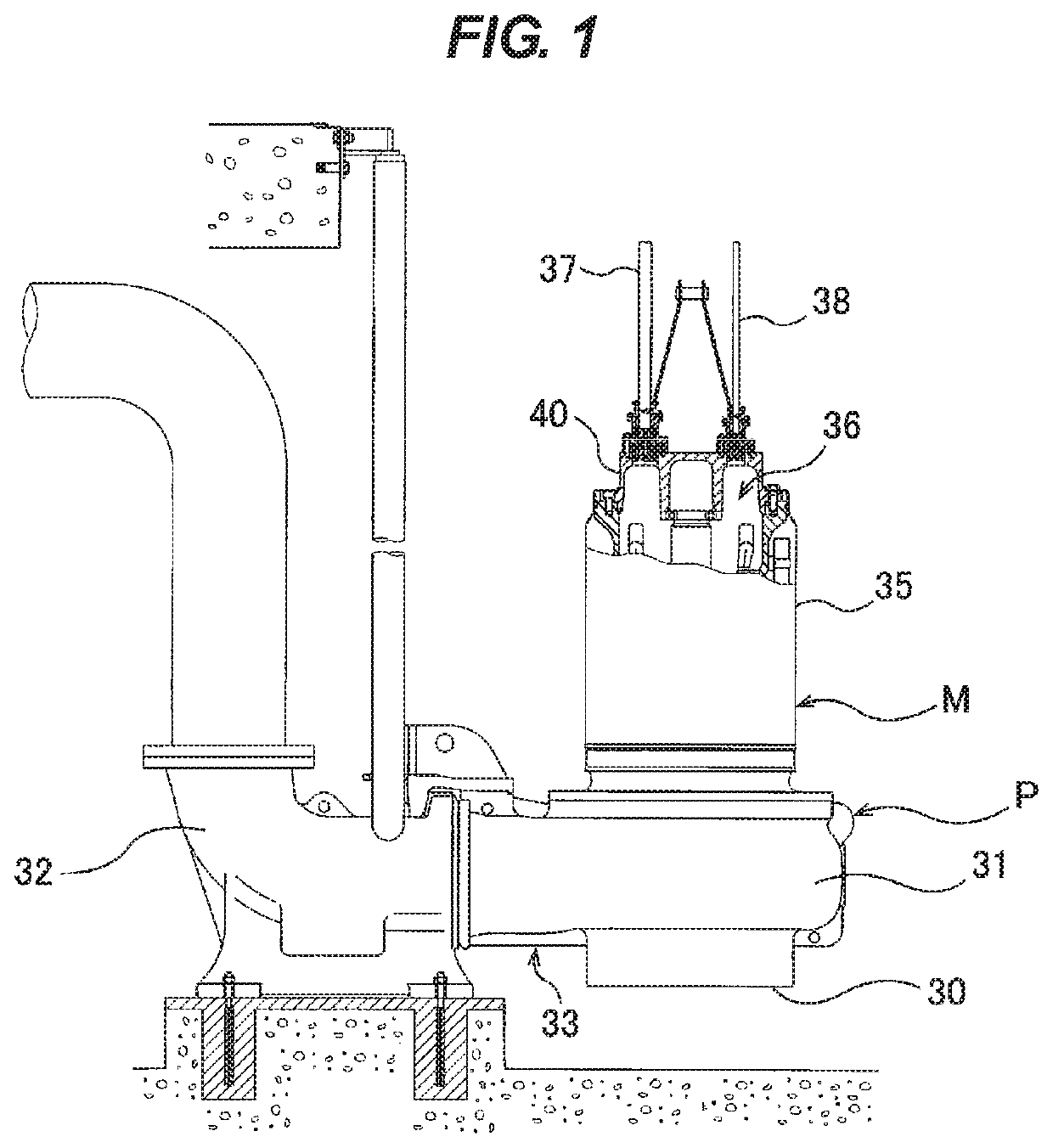
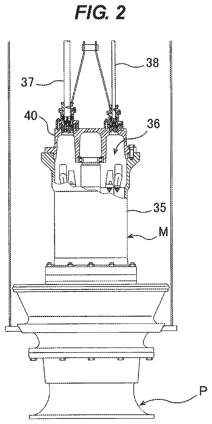
[0043]FIG. 1 is a diagram showing a submersible volute pump apparatus including a submersible motor according to an embodiment of the present invention. FIG. 2 is a diagram showing a submersible mixed flow pump apparatus including the submersible motor according to the embodiment of the present invention. As shown in FIGS. 1 and 2, the submersible motor can be applied to a submersible pump such as a submersible volute pump or a submersible mixed flow pump. A submersible volute...


PUM


Abstract

The present invention relates to a high-voltage submersible motor and a waterproof connector for use in the submersible motor. The submersible motor includes a motor body (36), a power cable (37a), a cable contact (50) electrically connected to the power cable (37a), a cable-side insulating member (49) to which the cable contact (50) is liquid-tightly coupled, a motor contact (42) connected to the cable contact (50), a motor-side insulating member (41) to which the motor contact (42) is liquid-tightly coupled, and an insulating resin (93) that fills an enclosed space (60) formed between the cable-side insulating member (49) and the motor-side insulating member (41). A connecting portion of the cable contact (50) and the motor contact (42) is covered with the resin (93).

Description

TECHNICAL FIELD[0001]The present invention relates to a submersible motor and a waterproof connector, and more particularly to a high-voltage submersible motor and a waterproof connector for use in the submersible motor.BACKGROUND ART[0002]Upon recent abnormal weather or a disaster such as a typhoon or a flood, conventional land-based pumps sometimes cannot be operated when they are required to work. Introduction of submersible pumps, which can be operated even when they are submerged, is a conceivable countermeasure, and replacement of a land-based pump with a submersible pump at the time of pump replacement is increasing these days.[0003]The introduction of a submersible pump necessitates the use of a submersible motor having an unprecedentedly large capacity. In particular, some overseas rivers and drainage pump stations are of a large scale and, in most cases, a high-power (1 MW-class) submersible motor is used for them.[0004]Submersible motors are becoming higher-voltage ones w...

Claims


Application Information

Patent Timeline
Patent Type & Authority Patents(United States)
IPC IPC(8): H01R13/40H02K5/22H01R13/52E21B17/02H01R13/523
CPCH01R13/5216H01R13/523H02K5/225H02K5/22H01R13/52H01R13/521E21B17/028H01R13/5205E21B17/0285
Inventor IMAFUKU, MASAAKIWATANABE, TAKURO
Owner EBARA CORP
Why Eureka
Try Eureka