Dose planning system

a technology of dose planning and dose, applied in the field of dose planning system, can solve the problems of difficult determination of correct dose and complicated delineation of tumour tissue, and achieve the effect of speeding up the diagnosis to the treatment process

Active Publication Date: 2020-06-30
KONINKLJIJKE PHILIPS NV
View PDF9 Cites 0 Cited by
  • Summary
  • Abstract
  • Description
  • Claims
  • Application Information

AI Technical Summary

Benefits of technology

[0016]Currently within radiation treatment two important challenges exist. The first is that precise delineation of tumour tissue may be complicated. A lot of variation exists between delineations made by different observers based on the medical images. Furthermore, determination of the correct dose may be challenging. It has been proposed to vary the dose within the tumour based on the tumour aggressiveness to increase tumour control probability and reduce side effects. However, this so-called dose painting by numbers approach always relies on (functional) imaging (e.g. PET, Diffusion Weighted MRI, Dynamic Contrast Enhanced MRI) of the tissue. It is an insight of the inventors that these imaging techniques only provide indirect measures of tumour probability and tumour aggressiveness. Therefore, by directly using the biopsy results to calculate a tumour probability map, which is in turn the input for a dose planning module, the treatment plan may be improved. The tumour probability map could be a map providing a spatial distribution of estimated chances of tumour presence. It could also provide a spatial distribution on expected tumour cell densities or aggressiveness levels (e.g. Gleason score in the case of prostate cancer).
[0018]According to a further embodiment of the invention, the image guided biopsy system comprises a photonic needle. Automatic analysis of the spectrum retrieved by the photonic needle would further speed up the diagnosis to treatment process.

Problems solved by technology

Currently within radiation treatment two important challenges exist.
The first is that precise delineation of tumour tissue may be complicated.
Furthermore, determination of the correct dose may be challenging.

Method used


Image

  • Dose planning system
  • Dose planning system
  • Dose planning system

Examples


Embodiment Construction

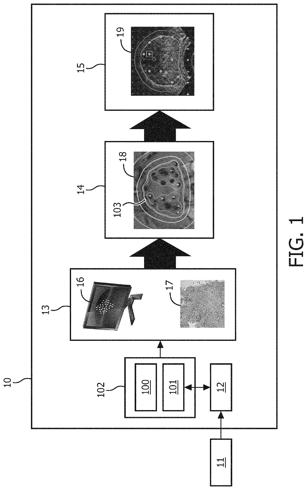
[0025]FIG. 1 shows a dose planning system 10 according to the invention. The dose planning system comprises a biopsy map creation module 13, a probability map calculation module 14 and a dose planning module 15. A dose planning workflow using the invention could start with the acquisition 11 of images of an organ of interest based on which the suspicious locations within the organ could be identified. Also non-suspicious locations could be identified. These images could for example be magnetic resonance (MR) images. The MR images could be provided to registration module 12. During a biopsy procedure, image guided biopsy system 102 could acquire ultrasound images for biopsy guidance by means of ultrasound system 101. At least one of the ultrasound images is provided to the registration module 12. The registration module then registers the ultrasound image with the MR image, such that the identified suspicious and non-suspicious locations of the organ can be translated to the imaging ...


PUM


Abstract

A dose planning system includes a biopsy map creation module configured for receiving biopsy information for an organ of interest regarding biopsy locations and tissue characteristics of tissue found at the biopsy locations and creating a spatially annotated biopsy map for the organ, by linking the spatial information on the biopsy locations to the tissue characteristics of tissue found at the corresponding biopsy locations. A probability map calculation module is configured for creating a tumor probability map by calculating a tumor probability for locations in the organ from which no biopsy was taken by using the tumor and / or tissue characteristics from the biopsy locations and a dose planning module configured for creating a dose plan based on the tumor probability map. The planning constraints are such that on average a higher tumor probability results in a higher planned dose and a lower tumor probability results in a lower planned dose.

Description

CROSS-REFERENCE TO PRIOR APPLICATIONS[0001]This application is the U.S. National Phase application under 35 U.S.C. § 371 of International Application Serial No. PCT / EP2016 / 063336, filed on Jun. 10, 2016, which claims the benefit of European Patent Application No. 15171904.4, filed on Jun. 12, 2015. This application is hereby incorporated by reference herein.FIELD OF THE INVENTION[0002]The invention relates to a dose planning system for a therapeutic treatment of diseased tissue of an organ and more specifically the invention relates to a dose planning system for treatment in the field of oncology.BACKGROUND OF THE INVENTION[0003]Treatment of tumours in cancer patients can be performed using several approaches, ranging from minimally invasive approaches such as brachytherapy to surgical approaches where the full organ containing the tumour is removed. Less invasive, focal therapies are gaining popularity due to improvements in early detection and screening, and the potentially reduce...

Claims


Application Information

Patent Timeline
Patent Type & Authority Patents(United States)
IPC IPC(8): A61B34/10A61B18/20A61N7/02A61B8/08A61B10/04A61B18/12G16H20/10A61B18/02A61N5/10A61B18/14A61B90/00A61B18/00A61B17/34A61B34/20
CPCA61B18/20A61N7/02A61B10/04A61B34/10A61B18/12G16H20/10A61N5/103A61N5/1031A61B8/0841A61N5/1001A61B18/02A61B2017/3413A61B18/14A61B2034/101A61B2018/00577A61B2090/378A61B2034/105A61N2005/1087A61B2090/365A61B2010/045A61B2034/2063A61B2090/364A61N5/10
Inventor KUSTRA, JACEK LUKASZHAUTVAST, GUILLAUME LEOPOLD THEODORUS FREDERIK
Owner KONINKLJIJKE PHILIPS NV
Why Eureka
Try Eureka