System for measuring residual stress in optical thin films in both transmission and reflection
a technology of transmission and reflection, applied in the direction of measurement devices, force measurement by measuring optical property variation, instruments, etc., can solve the problems of inability to use apparatus and failure to achieve the measurement of residual stress, and achieve the effect of reducing both the purchase cost and the maintenance cos
- Summary
- Abstract
- Description
- Claims
- Application Information
AI Technical Summary
Benefits of technology
Problems solved by technology
Method used
Image
Examples
first embodiment
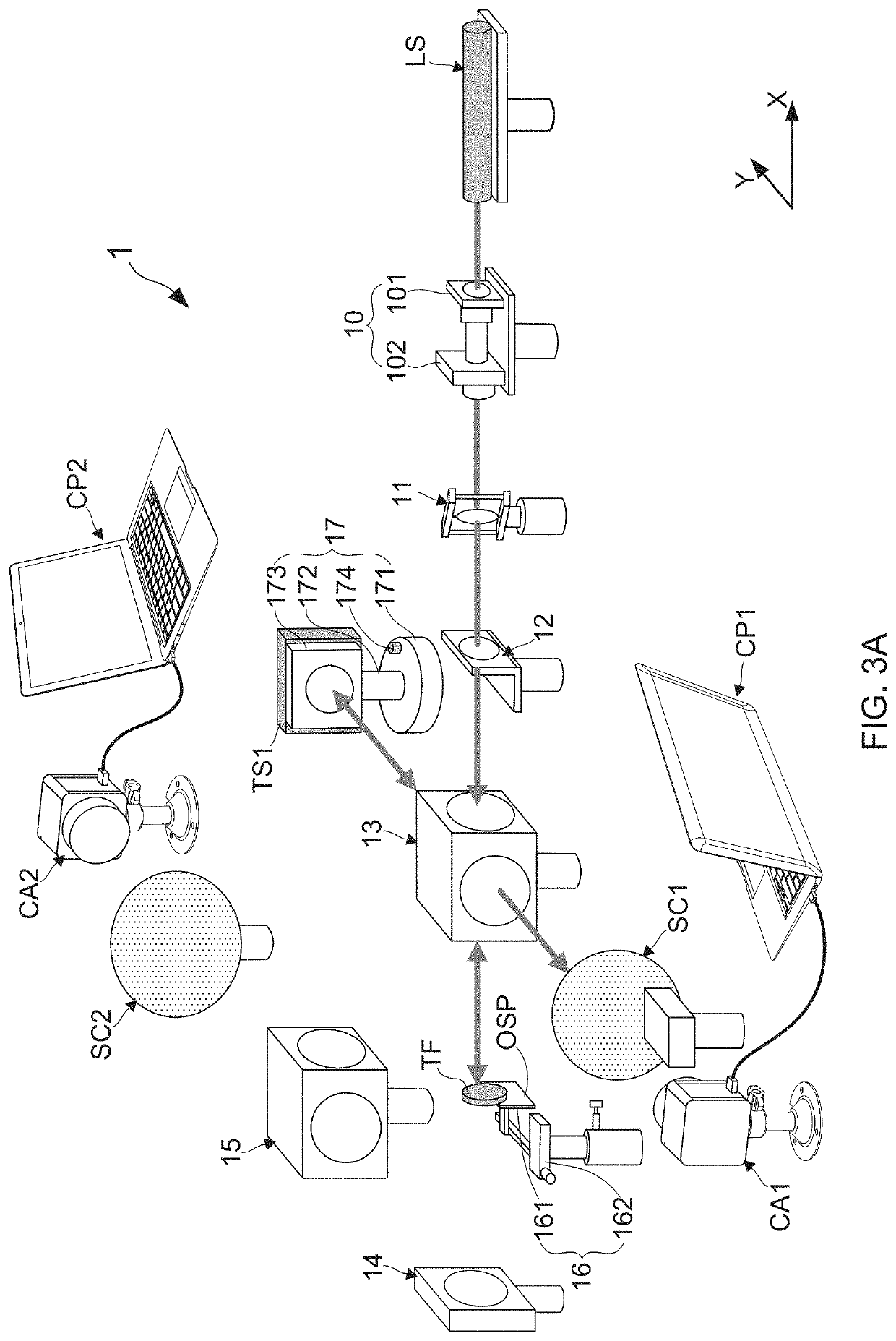
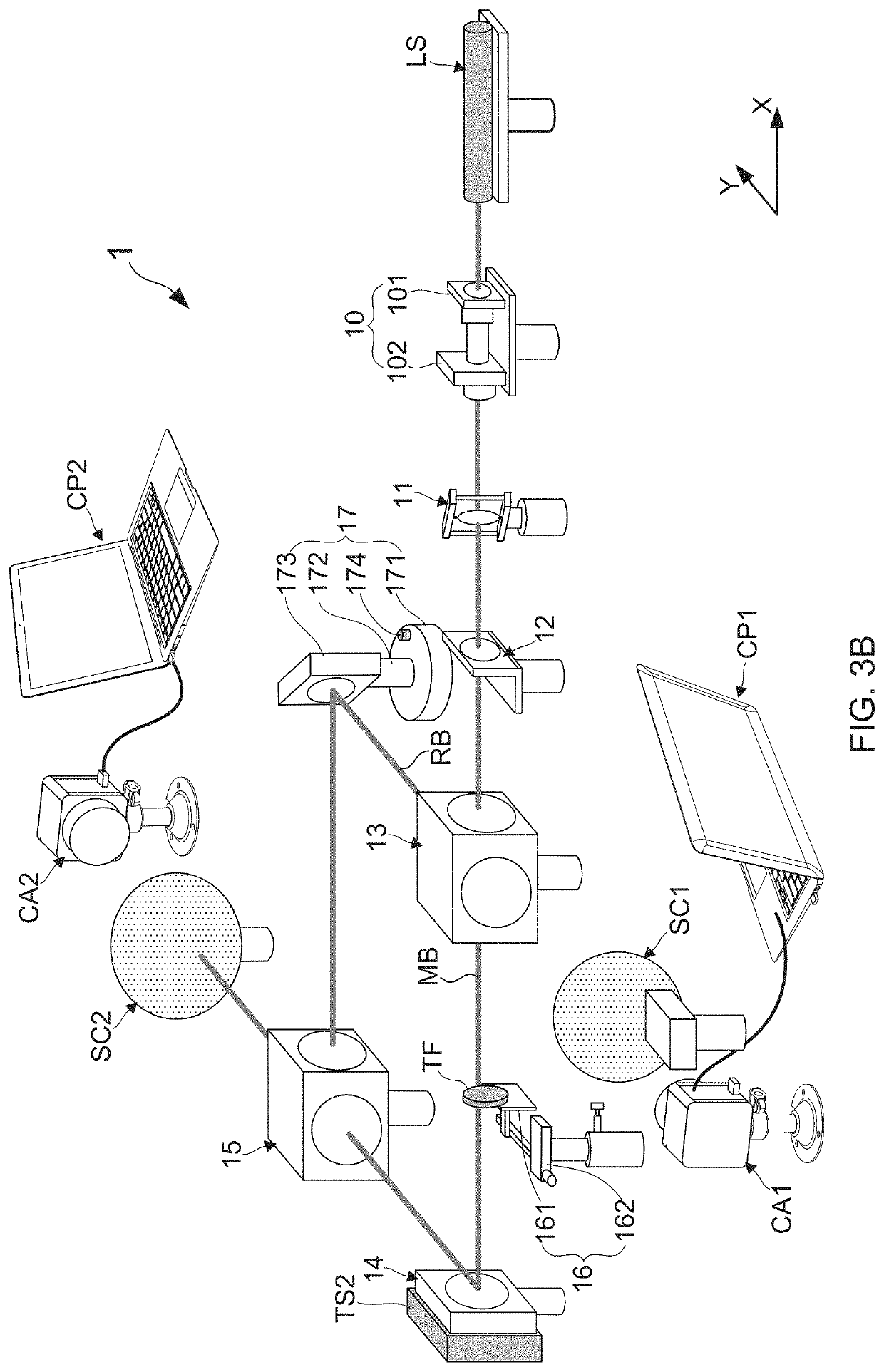
[0058]With reference to FIGS. 3A and 3B, there are provided framework views of a system for measuring residual stress in optical thin films according to the present invention. As FIG. 3A shows, the residual stress measuring system 1 proposed by the present invention comprises: a laser source LS, a spatial filter 10, a collimating lens module 11, an aperture module 12, a first beam splitter module 13, a test plate module 17, a sample carrying module 16, a first screen SC1, a first image capturing module CAL a reference plate 14, a second beam splitter module 15, a second screen SC2, a second image capturing module CA2, a first controlling and processing module CP1, and a second controlling and processing module CP2.
[0059]Following on from the previous descriptions, the laser source is a helium-neon laser device, which is provided herein for emitting a laser beam. Moreover, the spatial filter 10 is configured for receiving the laser beam and subsequently applying a spatial filtering p...
second embodiment
[0065]With reference to FIGS. 4A and 4B, there are provided framework views of the system for measuring residual stress in optical thin films according to the present invention. According to the second embodiment, the residual stress measuring system 2 proposed by the present invention also comprises: a laser source LS, a spatial filter 10, a collimating lens module 11, an aperture module 12, a first beam splitter module 13, a test plate module 17, a sample carrying module 16, a first screen SC1, a first image capturing module CAL a reference plate 14, a second beam splitter module 15, a second screen SC2, a second image capturing module CA2, a first controlling and processing module CP1, and a second controlling and processing module CP2. Differing from the above-described first embodiment, a first linear motion platform PS1 using piezoelectric transducer (PZT) device is arranged in the second embodiment for allowing the test plate 173 to be putted thereon. After the first linear m...
PUM
| Property | Measurement | Unit |
|---|---|---|
| turning angle | aaaaa | aaaaa |
| included angle | aaaaa | aaaaa |
| residual stress | aaaaa | aaaaa |
Abstract
Description
Claims
Application Information
 - R&D
- Intellectual Property
- Life Sciences
- Materials
- Tech Scout
- Unparalleled Data Quality
- Higher Quality Content
- 60% Fewer Hallucinations
Browse by: Latest US Patents, China's latest patents, Technical Efficacy Thesaurus, Application Domain, Technology Topic, Popular Technical Reports.
© 2025 PatSnap. All rights reserved.Legal|Privacy policy|Modern Slavery Act Transparency Statement|Sitemap|About US| Contact US: help@patsnap.com


