Valve positioner and user interface for valve positioner

a user interface and valve positioner technology, applied in the field of valve positioners, can solve the problems of increasing the risk of water ingress from every opening of the housing, cumbersome and time-consuming valve housing opening,

Active Publication Date: 2020-06-30
NELES FINLAND OY
View PDF14 Cites 0 Cited by
  • Summary
  • Abstract
  • Description
  • Claims
  • Application Information

AI Technical Summary

Benefits of technology

[0014]In an embodiment, the optical touch buttons comprise reflective optical sensors having a light emitter and a light receiver, and said one or more elements for controlling propagation of light is arranged to reduce cross talk from the light emitter to the light receiver.

Problems solved by technology

The opening of the housing is typically cumbersome and time consuming as the cover of the housing is often closed by screws or similar means.
The opening of the housing may sometimes be difficult (e.g. due to weather conditions or plant environment) or even impossible (e.g. forbidden by Ex regulations).
Every opening of the housing will be a further risk for water ingress.
While external buttons might provide easy access, there is a new problem related to the security of the LUI usage.
Furthermore, when the user interface is accessible by not opening the housing, there is always a risk of un-authorized access on purpose or by human mistake.
However, it would be frustrating and time consuming to enter a PIN code (i.e. an access code) every time the local user interface is used, especially during start up configuration of the positioner.
Further, there can be a high number of positioners and control valves, often hundreds of them, in a single plant, typically from several vendors, so that it would be a challenging task to manage and remember PIN codes for all positioners.

Method used


Image

  • Valve positioner and user interface for valve positioner
  • Valve positioner and user interface for valve positioner
  • Valve positioner and user interface for valve positioner

Examples


Embodiment Construction

[0038]The invention relates to valve positioners, and particularly to user interfaces of smart valve positioners.

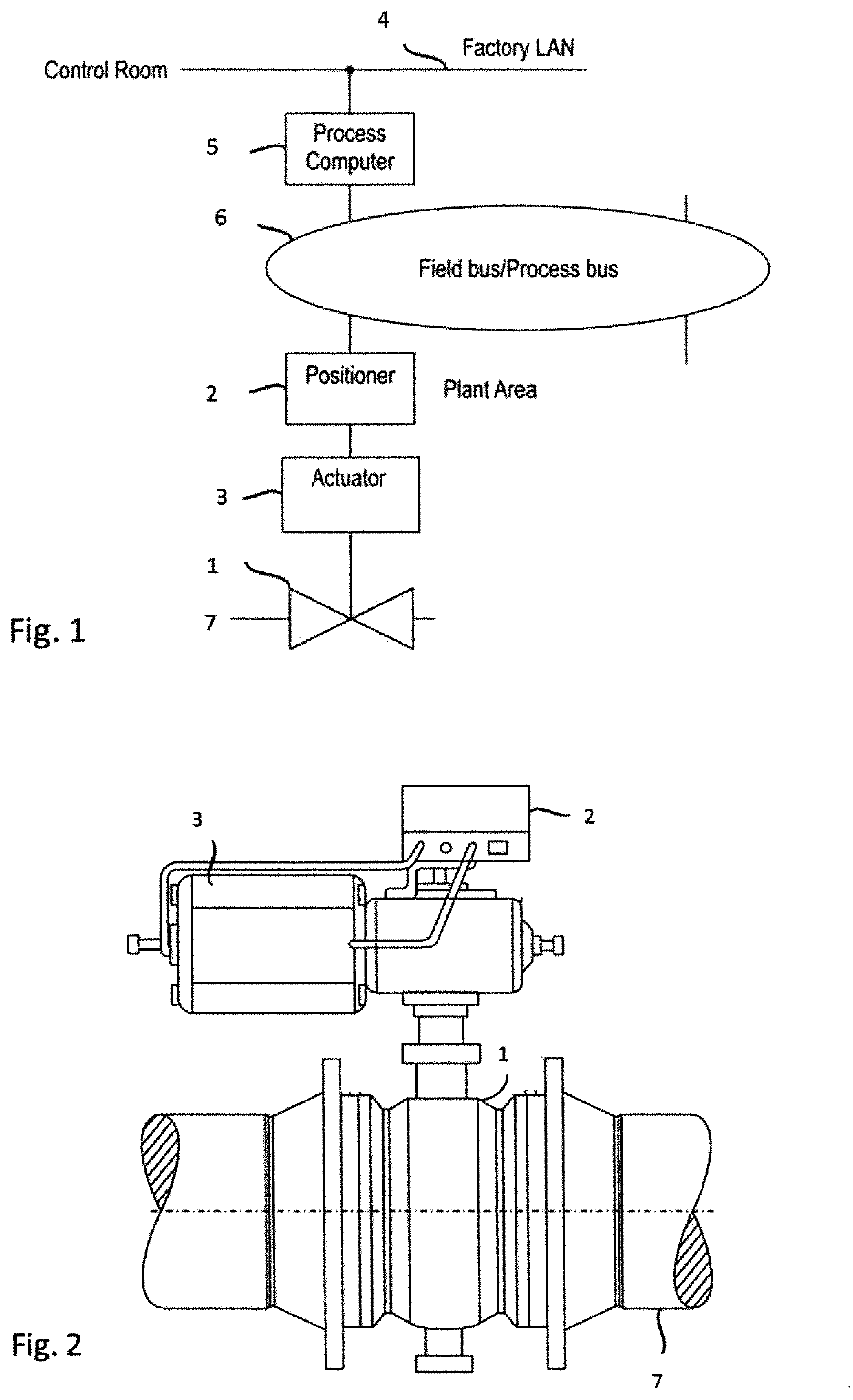
[0039]FIG. 1 shows a schematic block diaphragm of an exemplary process automation system wherein the principles of the invention may be applied in a valve positioner. The control system block 5 generally represents any and all control room computer(s) / programs and process control computer(s) / programs as well as databases, which may be interconnected by a factory LAN 4, in the automation system. There are various architectures for a control system. For example, the control system may be a Direct Digital Control (DDC) system or Distributed Control System (DCS), both well known in the art. It should be appreciated that the type or architecture of the automation system is not relevant to the present invention

[0040]In the example of FIG. 1, a control valve assembly comprising a process valve 1 and a positioner 2 and an actuator 3 may be connected to a process to control the fl...


PUM

PropertyMeasurementUnit
dielectric constantaaaaaaaaaa
timeaaaaaaaaaa
thicknessaaaaaaaaaa

Abstract

A smart valve positioner is provided with a local user interface with non-mechanical touch buttons and a display inside a positioner housing under a housing cover for locally operating the valve positioner. The touch buttons are user-operable by touching the touch buttons when the housing cover is open. The housing cover is arranged to make the touch buttons user-operable from outside the housing by touching the housing cover, when the housing cover is closed.

Description

FIELD OF THE INVENTION[0001]The invention relates to valve positioners, and particularly to user interfaces of smart valve positioners.BACKGROUND OF THE INVENTION[0002]A control valve is generally used for a continuous control of a liquid or gas flow in different pipelines and processes. In a processing industry, such as pulp and paper, oil refining, petrochemical and chemical industries, different kinds of control valves installed in a plant's pipe system control material flows in the process. A material flow may contain any fluid material, such as fluids, liquors, liquids, gases and steam. The control valve is usually connected with an actuator, which moves the closing element of the valve to a desired position between fully open and fully closed positions. The actuator may be a pneumatic cylinder-piston device, for example. The actuator, for its part, is usually controlled by a valve positioner, also called as a valve controller, which controls the position of the closing element...

Claims


Application Information

Patent Timeline
Patent Type & Authority Patents(United States)
IPC IPC(8): G06F3/041F15B15/28F16K31/122G02F1/1333G05B19/44H03K17/96G05D7/06F16K31/12A01G25/16
CPCF16K31/122G02F1/13338H03K17/962F15B15/2815F16K31/12G06F3/0416G05B19/44G05D7/0623H03K17/9631G05B2219/25257H03K2217/960775G05B2219/25312G05B2219/23377A01G25/16G05B2219/23044H03K2217/96015G06F1/1607F16K27/12G06F3/0488
Inventor IHALAINEN, TEROYLI-PETÄYS, JUHA
Owner NELES FINLAND OY
Why Eureka
Try Eureka