
Frac pump valve assembly

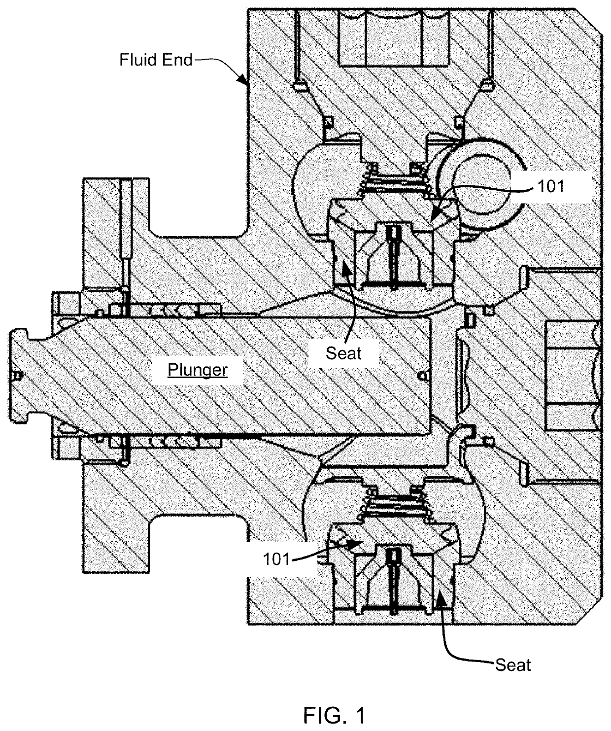
a valve assembly and valve technology, applied in the direction of pump parameters, positive displacement liquid engines, liquid fuel engines, etc., can solve the problems of valve fracturing, valve is subjected to course contaminants, valve wear, premature wear, erosion, etc., to reduce the effect of wear, erosion, and fractur

Active Publication Date: 2020-07-14
ST9 GAS & OIL LLC
View PDF20 Cites 20 Cited by
  • Summary
  • Abstract
  • Description
  • Claims
  • Application Information

AI Technical Summary

Benefits of technology

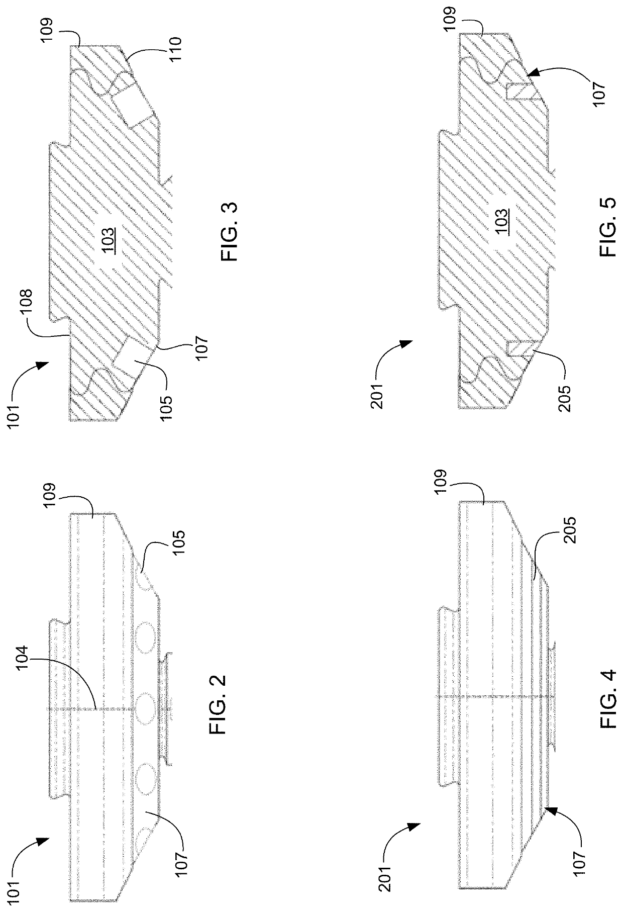
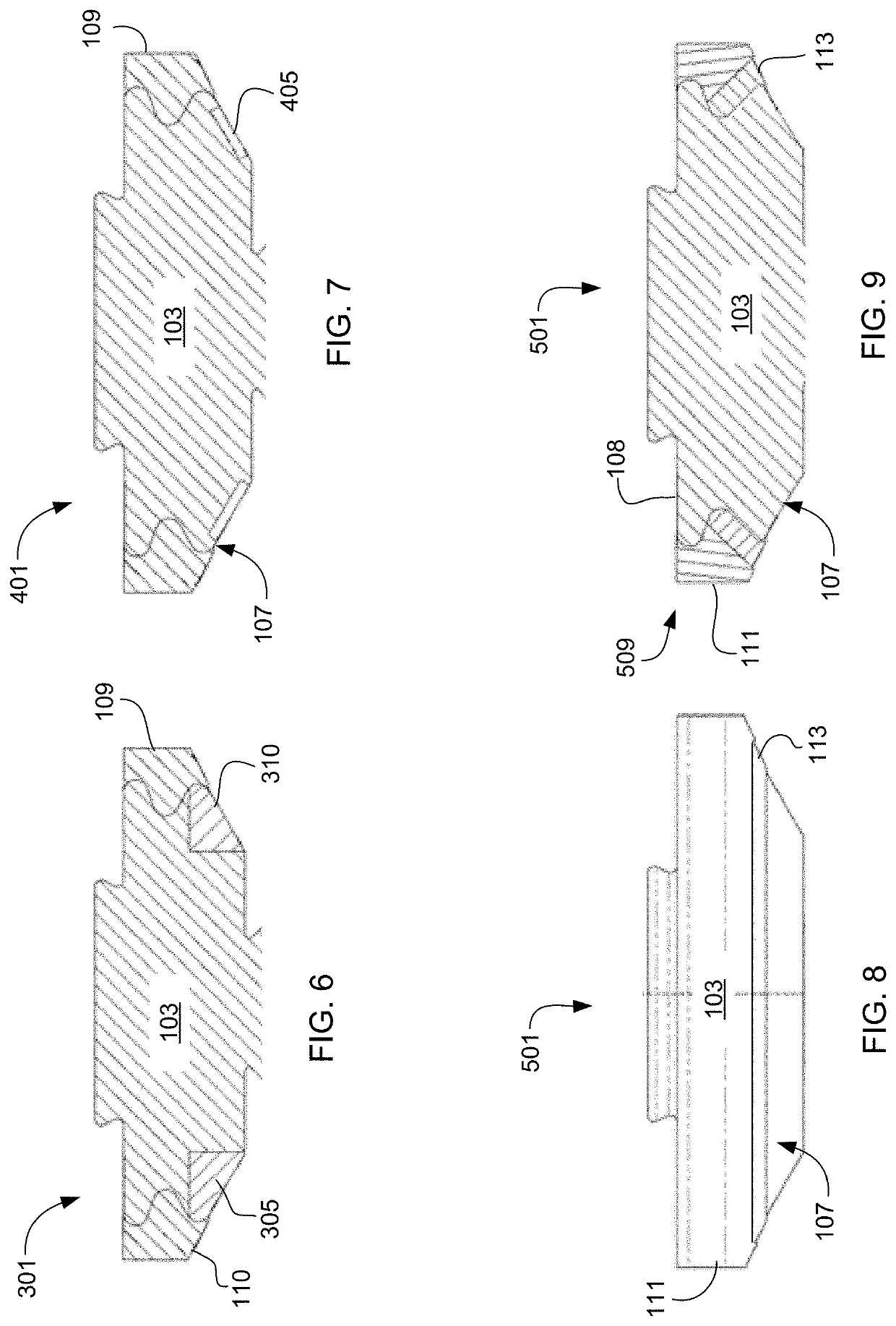
[0007]It is an object of the present application to provide a column or insert of a supplemental material onto a surface of the valve to minimize the effects of wear, erosion, and fracture from the contaminants and pressures inside the fluid end. The hardness of the supplemental material being greater than the hardness of the valve body.
[0008]It is a further object of the present application to provide a valve assembly configured to include a dual material seal on the valve body to also mitigate the effects of wear, erosion, and fracture around the periphery of the valve. The dual seal material The dual seal includes a first material and a second material. Each has different hardness levels. The hardness level of the second material is greater than the first material. The material with the higher hardness level is adjacent the contact surface of the valve body. Ultimately the invention may take many embodiments. In this way, this assembly overcomes the disadvantages inherent in the prior art.

Problems solved by technology

A number of issues can arise with conventional valves in fluid ends.
Each valve is subjected to the course contaminants within the fracture fluid and the repetitive or cyclical contacting of the seat.
Over time, the combination of the course fracture fluid with the repetitive contact forces from the seat can lead to premature wear, eroding, and fracturing of the valve during operation.
The same course contaminants tend to wear the seal resulting in erosion and the development of fractures therein.
The constant repetitive impacting of the valve surface on the seat can greatly damage the valve surface immediately adjacent to the seal area as the transition between materials occurs.

Method used


Image

  • Frac pump valve assembly
  • Frac pump valve assembly
  • Frac pump valve assembly

Examples


Embodiment Construction

[0023]Illustrative embodiments of the preferred embodiment are described below. In the interest of clarity, not all features of an actual implementation are described in this specification. It will of course be appreciated that in the development of any such actual embodiment, numerous implementation-specific decisions must be made to achieve the developer's specific goals, such as compliance with system-related and business-related constraints, which will vary from one implementation to another. Moreover, it will be appreciated that such a development effort might be complex and time-consuming but would nevertheless be a routine undertaking for those of ordinary skill in the art having the benefit of this disclosure.

[0024]In the specification, reference may be made to the spatial relationships between various components and to the spatial orientation of various aspects of components as the devices are depicted in the attached drawings. However, as will be recognized by those skille...


PUM


Abstract

A valve assembly includes a valve body, a seal, and a supplemental material. The valve assembly configured to reduce the effects of wear and erosion of the seal and valve body by including material with increased hardness. The supplemental material has a higher hardness level than the valve body and is inserted on the contact surface of the valve body. The seal can include a plurality of materials, each having different hardness levels. The location of the supplemental material can vary and the overall radial distribution on the contact surface may vary.

Description

CLAIM OF PRIORITY[0001]This application claims the benefit of U.S. Provisional Application No. 62 / 486,802 filed 18 Apr. 2017. The information contained therein is hereby incorporated by reference.BACKGROUND1. Field of the Invention[0002]The present application relates generally to a reciprocating pump, and in particular to a valve assembly for use with either a suction or discharge valve in a fluid end.2. Description of Related Art[0003]Hydraulic fracturing can increase the rate of production of oil and gas from low-permeability reservoirs. Hydraulic fracturing increases the permeability of reservoir rocks by opening channels through which oil and gas can travel to recovery wells. During hydraulic fracturing, a fluid is pumped through a wellbore under high pressure into a subterranean reservoir where it splits or fractures the reservoir rock. A proppant, like sand, is often added to the pumped fracture fluid and carried in suspension into the newly formed fractures. When pumping cea...

Claims


Application Information

Patent Timeline
Patent Type & Authority Patents(United States)
IPC IPC(8): F04B53/10F16K25/00
CPCF04B53/1075F04B53/108F04B53/1087F16K25/005F04B2201/0603
Inventor BUCKLEY, CHRIS
Owner ST9 GAS & OIL LLC
Learn More