
Systems and methods for a robotic-assisted revision procedure

a robotic and assisted surgery technology, applied in the field of robotic assisted orthopedic surgery, can solve the problems of increased bone loss, difficult to perform, and inability to always accurately diagnose, and achieve the effect of dispensing the bone implant and minimizing overcutting the bon

Active Publication Date: 2020-07-21
MAKO SURGICAL CORP
View PDF12 Cites 9 Cited by
  • Summary
  • Abstract
  • Description
  • Claims
  • Application Information

AI Technical Summary

Benefits of technology

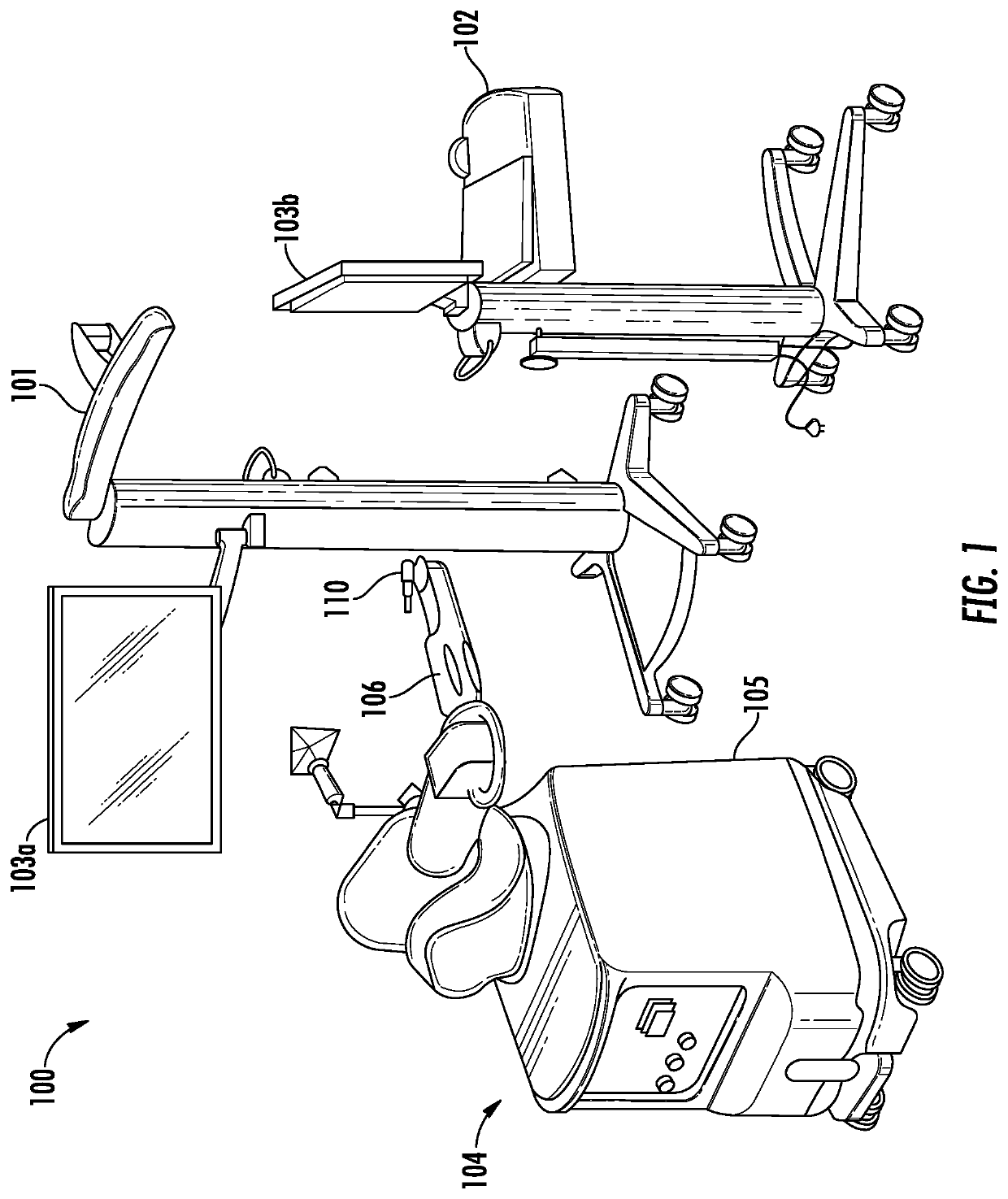
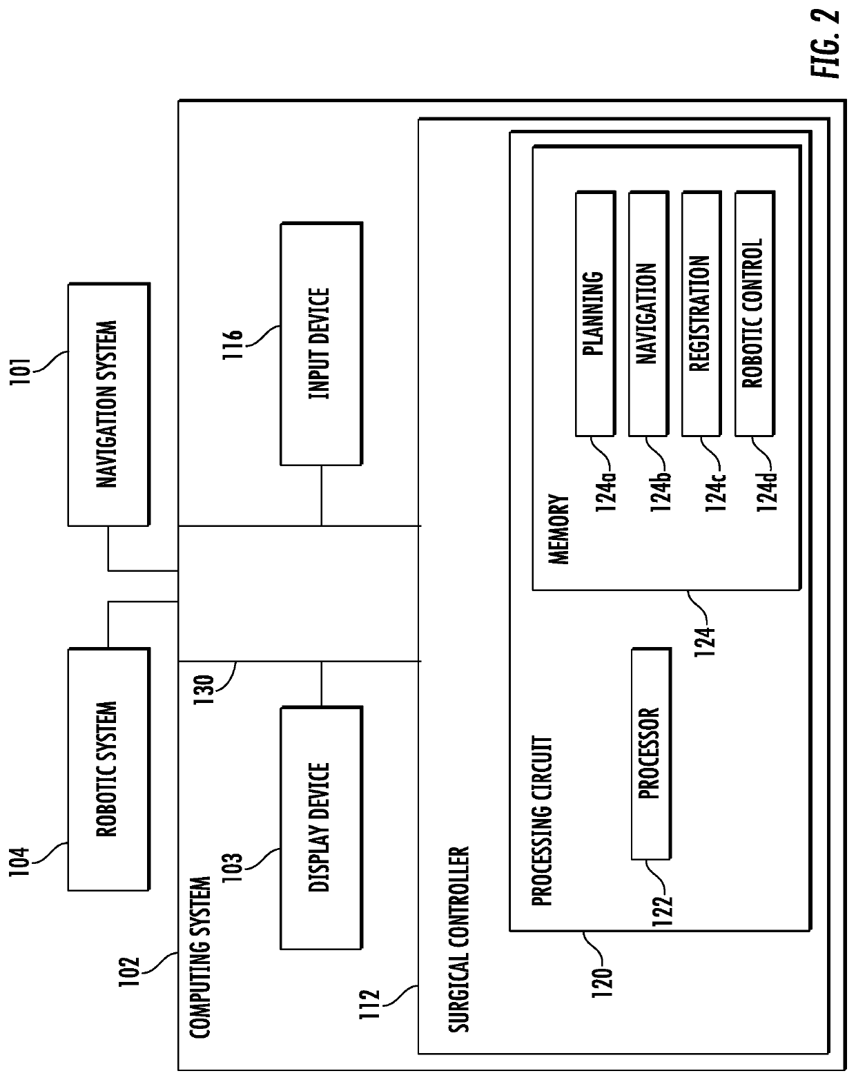
[0013]In an embodiment, a robotic system is used to assist in a knee or hip revision procedure. The robotic system may include a navigation system to register real bone to pre-scan CT images and precisely guide a robot arm to navigate through the patient anatomical space. The robotic system may have haptic capability, wherein the user can shape the haptic volume based on patient anatomy to protect the important bone structure and soft tissues (such as ligaments, nerves, and veins). The system may further include a flexible end effector, having multiple degrees of freedom and can be bent 90 degrees in any direction to allow the cutting tool, attached to the flexible arm, to access small area to dissect the bone implant. The system may have a large database which saves patient bone models and implant models and planning history during their primary knee or hip procedure, with the information being available for use in revision cases.
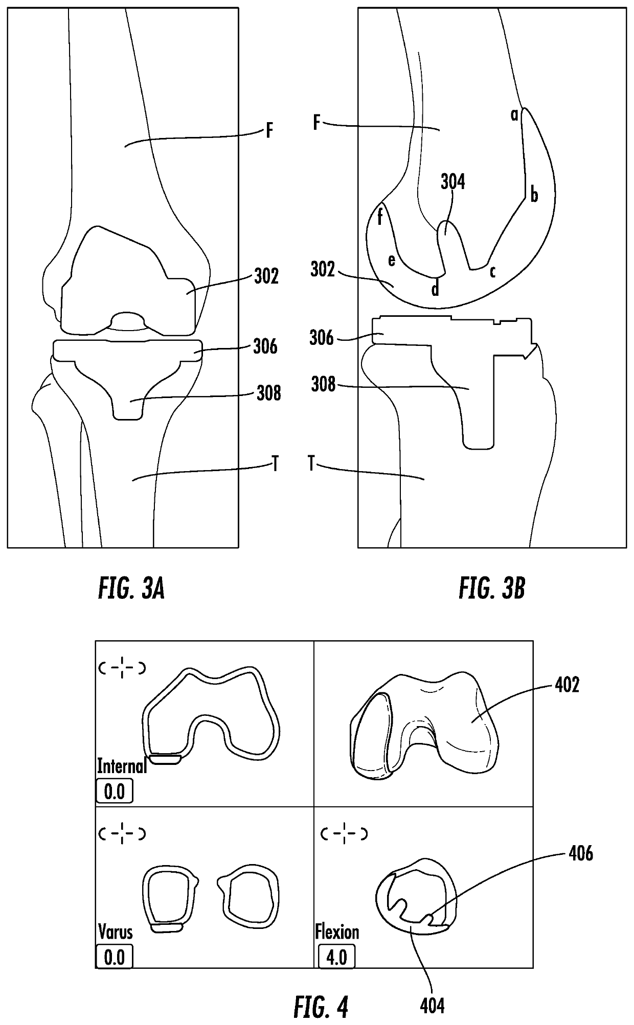
[0014]In another embodiment, the robotic system, using patient's previous / primary knee and hip information, can assist in revision cases by using a patient's previous / primary knee and hip implant model to create a revision haptic boundary to haptically guide the revision procedure; using a patient's previous / primary knee and hip bone model to register the bone to robot coordinate, wherein the patient does not need to take an extra CT image for the revision case; and using patient's previous / primary knee and hip planning information to identify the relative position between bone and implant in the revision case, wherein there is no relative motion between bone and implant, the implant surface is used to register the bone to robot coordinate.
[0015]In some embodiments, the robotic system creates a customized revision haptic boundary to protect overcutting of the bone and minimizing the bone lost during the revision procedure.
[0016]In some embodiments, the robotic system, based on the primary knee and hip implant model, precisely creates the revision haptic boundary around the primary implant to constraint the cutting tool and minimize overcutting the bone. In some embodiments, one of the following methods is used to register the implant and bone to primary knee and hip CT image during the revision: a trackable probe to digitize the implant surface and then register the bone to primary CT image; taking a few fluoroscopic images; and / or attaching a camera or optical sensor to the robot to scan the implant surface and then register it to the primary CT bone model. In some embodiments, the robotic system includes a dexterous flexible end effector system, the flexible end effector having multiple degrees of freedom and bendable in omni-direction to allow robot cut bone with constraint access space, and the flexible end effector carrying a high-speed rotating burr for cutting bone. In some embodiments, a video camera or ultrasound device is used to create an initial bone or implant model and / or to register the bone with the bone model.

Problems solved by technology

This manual surgery is not always accurate, is difficult to perform, and could result in greater bone loss than desired, which lessens the strength and integrity of the bone.
The limited access and occurrence of inaccurate cutting, removing of the implant, and cementation of the implant can cause significant bone loss.
The timing of the surgery, however, may be critical for the patient due to duration of the anesthesia.
In addition, performing such a procedure requires significant training.

Method used


Image

  • Systems and methods for a robotic-assisted revision procedure
  • Systems and methods for a robotic-assisted revision procedure
  • Systems and methods for a robotic-assisted revision procedure

Examples


Embodiment Construction

[0028]Before turning to the figures, which illustrate the exemplary embodiments in detail, it should be understood that the application is not limited to the details or methodology set forth in the description or illustrated in the figures. It should also be understood that the terminology is for the purpose of description only and should not be regarded as limiting.

[0029]The present disclosure introduces a robotic assisted approach to support a revision procedure of a joint, such as the knee joint or the hip joint, by allowing precise removal of a primary implant with minimal bone loss and while reducing the time needed to remove the primary implant. When bone loss is minimized, the number of revision procedures that may be performed on an individual patient during their lifetime increases.

[0030]Though the present disclosure makes reference to the knee and the hip joint, and revisions for the knee and the hip, the systems and methods disclosed herein are equally applicable to other...


PUM


Abstract

A method for performing a revision surgery using a robotic-assisted surgery system includes determining information related to an interface area between an implant component and a bone, and generating a planned virtual boundary associated with a portion of the interface area to be removed in a representation of the implant and the bone, based at least in part on the information related to the interface area. The method further includes tracking movement in the physical space of a cutting tool such that movement of the cutting tool is correlated with movement of a virtual tool, and providing a constraint on the cutting tool while the cutting tool removes the portion of the interface area. The constraint is based on a relationship between the virtual tool and the planned virtual boundary. The portion of the interface area is removed to remove the implant component from the bone.

Description

CROSS-REFERENCE TO RELATED PATENT APPLICATIONS[0001]This application claims priority to and the benefit of U.S. Provisional Patent Application No. 62 / 363,037, filed Jul. 15, 2016, which is hereby incorporated by reference in its entirety.BACKGROUND[0002]The present disclosure is related to robotic assisted orthopedic surgeries, and in particular, to robotic assisted revision surgeries.[0003]Currently, surgeons perform revision surgeries, such as revision knee and hip procedures manually. This manual surgery is not always accurate, is difficult to perform, and could result in greater bone loss than desired, which lessens the strength and integrity of the bone. The limited access and occurrence of inaccurate cutting, removing of the implant, and cementation of the implant can cause significant bone loss. During the procedure, surgeons may use a chisel and micro saw to manually dissect the implant. The surgeon has to perform this approach very slowly in order to preserve the bone. The ...

Claims


Application Information

Patent Timeline
Patent Type & Authority Patents(United States)
IPC IPC(8): A61B34/20A61B6/03A61B8/08A61B17/15A61B17/17A61B5/055A61B34/30A61B90/00A61B34/10
CPCA61B6/032A61B5/055A61B17/1703A61B34/20A61B17/15A61B90/361A61B8/0875A61B34/30A61B2090/3983A61B90/37A61B2034/105A61B2034/102A61B2034/2055A61B2034/2065A61B34/76A61F2/4607A61B34/10A61F2002/4632
Inventor KREBS, VIKTORKANG, HYOSIGKASODEKAR, SNEHALHARROW, MATTDING, JIENANCHANG, TA-CHENGWU, MINGONZALEZ, JEANEBBITT, PETER
Owner MAKO SURGICAL CORP
Learn More