Centrifugal blower, air conditioning apparatus, and refrigerating cycle apparatus
a centrifugal blower and air conditioning technology, applied in the direction of liquid fuel engine components, pump components, non-positive displacement fluid engines, etc., can solve the problems of wind noise and noise, and achieve the effects of reducing noise, enhancing efficiency, and reducing the flow in the casing
- Summary
- Abstract
- Description
- Claims
- Application Information
AI Technical Summary
Benefits of technology
Problems solved by technology
Method used
Image
Examples
first embodiment
(Configuration of Air Conditioning Apparatus)
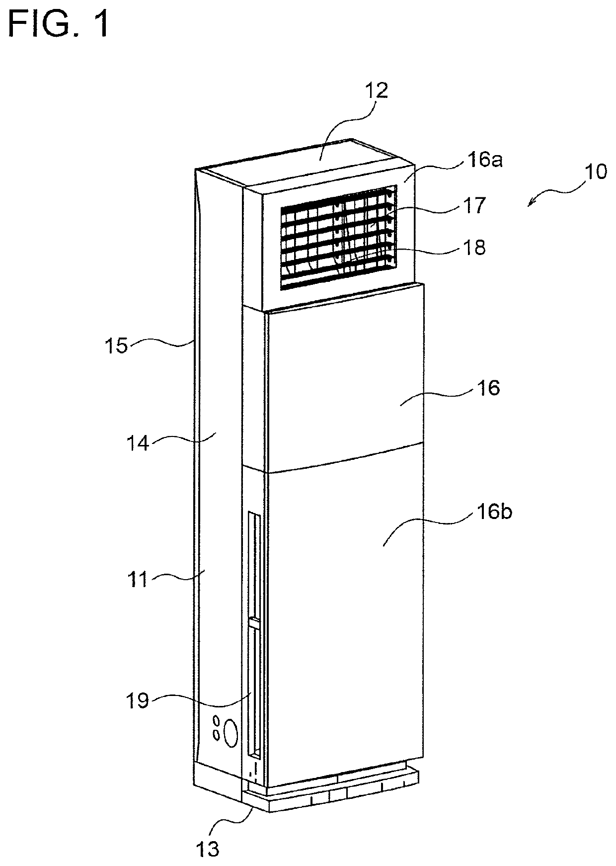
[0024]FIG. 1 is a perspective view showing an external shape of an air conditioning apparatus according to a first embodiment of the present invention. Specifically, the air conditioning apparatus according to the first embodiment is an indoor unit of a so-called packaged air conditioner, and is used in combination with an outdoor unit.
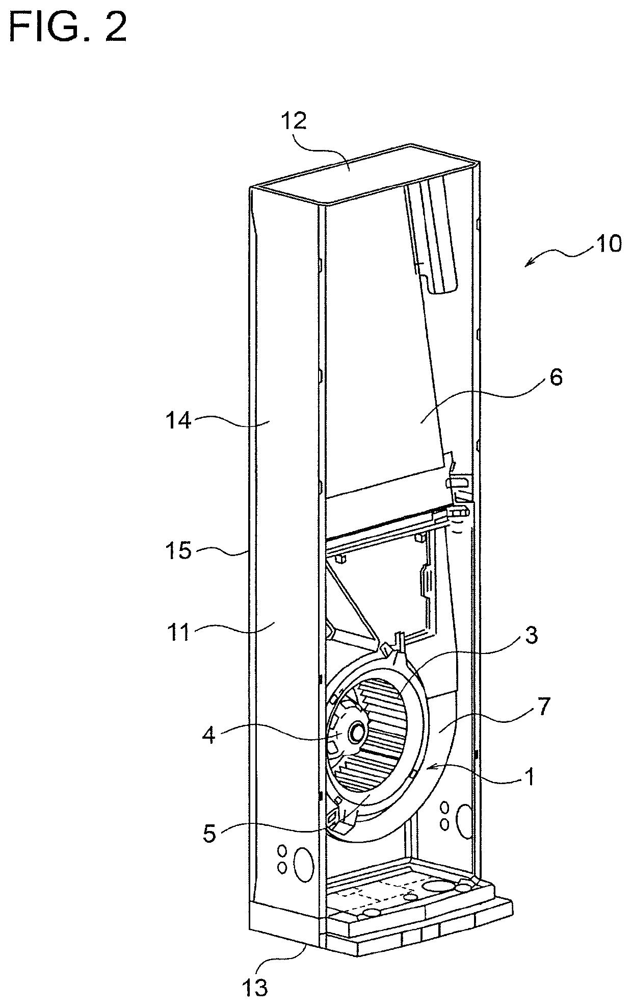
[0025]As shown in FIG. 1, the air conditioning apparatus 10 includes a housing 11 set on a floor of an air conditioning object space (an inside of a room). In this example, the housing 11 includes a top surface part 12, a bottom surface part 13, side surface parts 14, a back surface part 15, and a front surface part 16.
[0026]An outlet port 17 is formed in an upper part of the front surface part 16. The outlet port 17 is, for example, an opening having a rectangular shape. The outlet port 17 is provided with a plurality of vanes 18 for controlling wind direction. The vanes 18 are configured to be able to adj...
embodiment
Effect of Embodiment
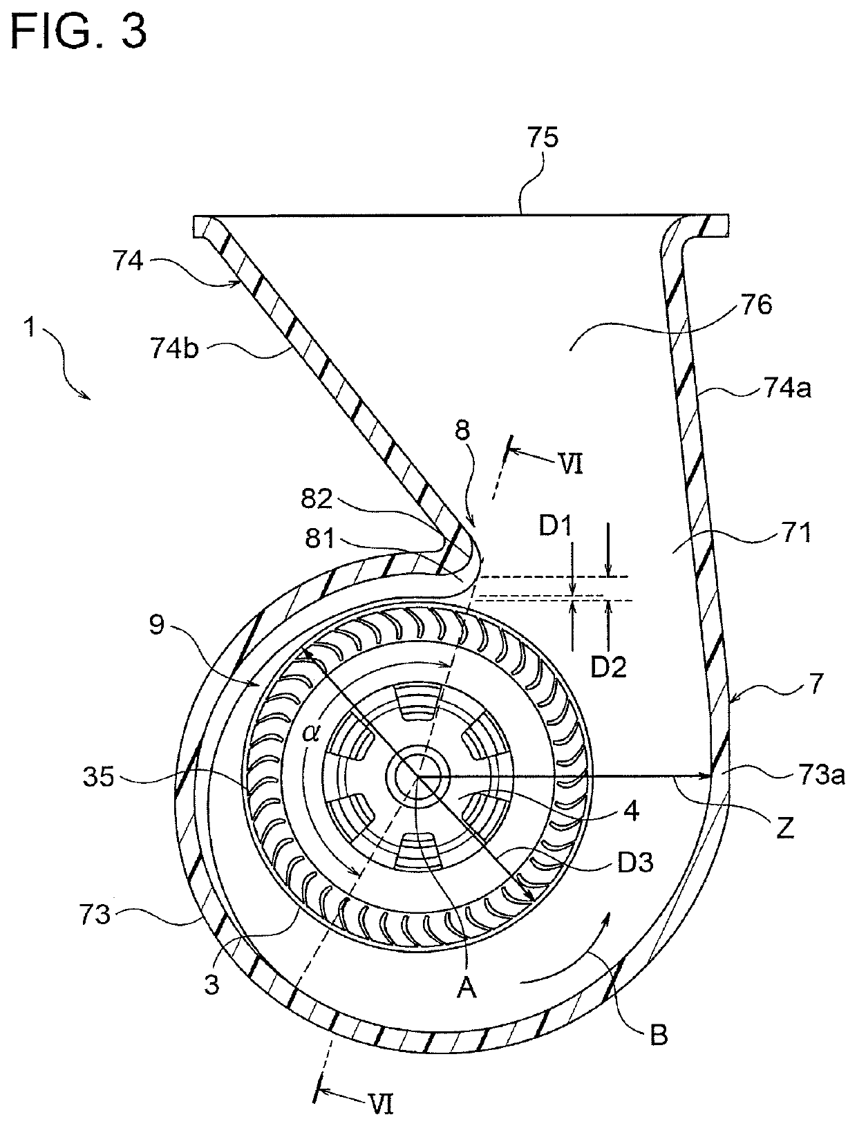
[0073]As described above, in the first embodiment of the present invention, the distance between the outer circumferential edge 35 of the centrifugal fan 3 and the tongue portion 8 is smaller on the main plate 31 side of the centrifugal fan 3 than on the side plate 32 side of the centrifugal fan 3. Thus, the circulating flow in the casing 7 can be reduced by reducing the distance between the outer circumferential edge 35 of the centrifugal fan 3 and the tongue portion 8 on the main plate 31 side of the centrifugal fan 3, and the noise can be reduced by securing a distance between the outer circumferential edge 35 of the centrifugal fan 3 and the tongue portion 8 on the side plate 32 side of the centrifugal fan 3. Thus, the noise can be reduced, and the efficiency can be enhanced.
[0074]Further, since the distance between the rotation axis A of the centrifugal fan 3 and the peripheral wall 73 of the casing 7 increases in the rotating direction of the centrifugal fa...
second embodiment
[0084]Next, a second embodiment of the present invention will be described below with reference to FIG. 10. FIG. 10 is a cross-sectional view showing a configuration of a centrifugal blower 1A according to the second embodiment. FIG. 10 corresponds to a cross-sectional view taken along a line VI-VI in FIG. 3 and viewed in a direction of arrows. In FIG. 10, components identical to those in the first embodiment are assigned the same reference characters as in the first embodiment.
[0085]In the second embodiment, a boundary portion 83 between the first part 81 and the second part 82 of the tongue portion 8 is inclined with respect to a plane perpendicular to the rotation axis A of the centrifugal fan 3. More specifically, the boundary portion 83 is configured so that the distance between the outer circumferential edge 35 of the centrifugal fan 3 and the tongue portion 8 increases continuously from the main plate 31 side toward the side plate 32 side of the centrifugal fan 3 (i.e., from ...
PUM
 Abstract
Description
Claims
Application Information
 - R&D
- Intellectual Property
- Life Sciences
- Materials
- Tech Scout
- Unparalleled Data Quality
- Higher Quality Content
- 60% Fewer Hallucinations
Browse by: Latest US Patents, China's latest patents, Technical Efficacy Thesaurus, Application Domain, Technology Topic, Popular Technical Reports.
© 2025 PatSnap. All rights reserved.Legal|Privacy policy|Modern Slavery Act Transparency Statement|Sitemap|About US| Contact US: help@patsnap.com


