
Enhanced vehicle efficiency using airfoil to raise rear wheels above road surface

a technology of rear wheels and airfoil, which is applied in the field of vehicles to achieve the effects of reducing emissions, reducing vehicle body weight, and preventing or reducing high wind

Active Publication Date: 2020-08-04
AUTAERO LLC
View PDF28 Cites 1 Cited by
  • Summary
  • Abstract
  • Description
  • Claims
  • Application Information

AI Technical Summary

Benefits of technology

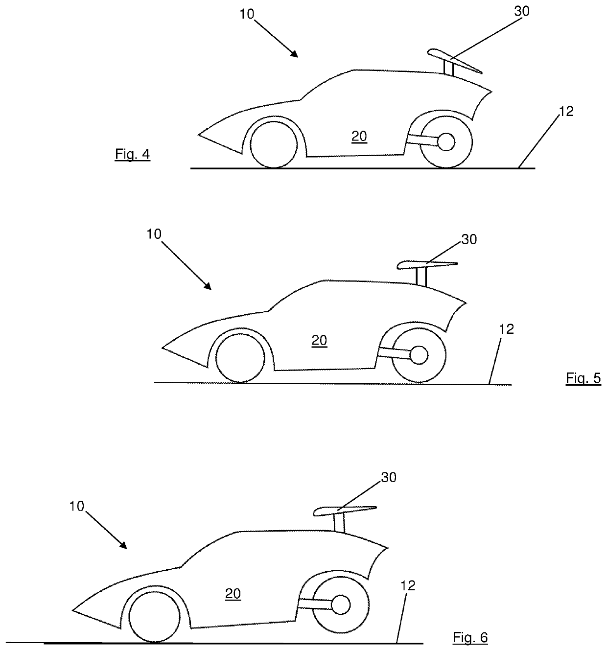
This patent describes a vehicle design that uses a wing to create lift to keep the rear wheels off the ground, resulting in a more efficient and comfortable ride. The wing automatically adjusts its angle of attack based on changes in air speed, and its position relative to the vehicle's center of mass. By adjusting the pitch of the wing, the vehicle can create sufficient lift to reduce friction with the road surface and improve ride quality. The vehicle can achieve a cruising speed of 50 to 120 mph, with a preferred speed of 65-80 mph. The design can be used in various vehicles such as bicycles, scooters, or motorcycles.

Problems solved by technology

This may cause the wing to automatically adjust its angle of attack, without any controls rotating the wing, due only to changes in relative air speed.

Method used


Image

  • Enhanced vehicle efficiency using airfoil to raise rear wheels above road surface
  • Enhanced vehicle efficiency using airfoil to raise rear wheels above road surface
  • Enhanced vehicle efficiency using airfoil to raise rear wheels above road surface

Examples


Embodiment Construction

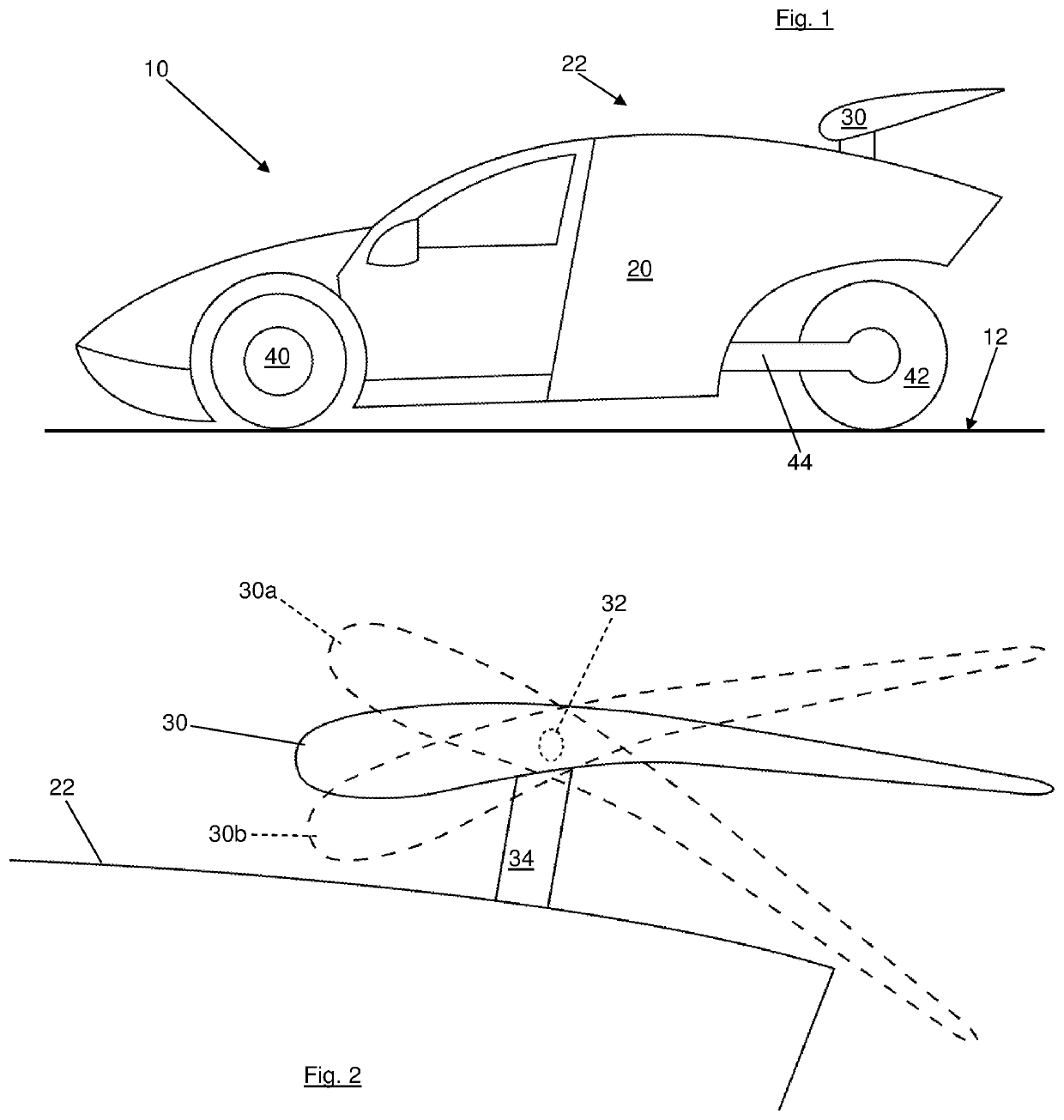
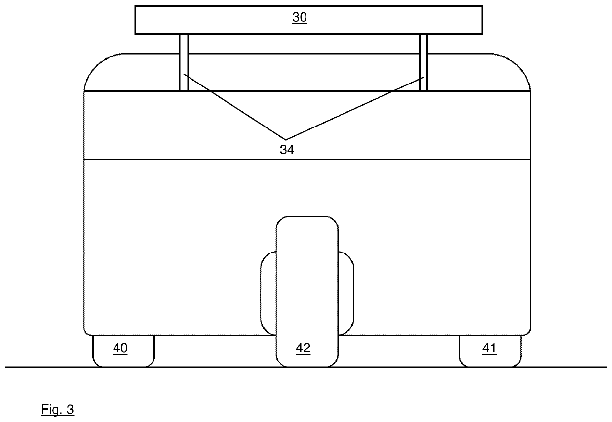
[0024]A vehicle 10 that may operate according to the invention is shown in FIG. 1. The vehicle 10 has a body 20 with an upper body surface, which may be a roof 22, and an airfoil, such as the wing 30, attached to the rear section of the body. The wing 30 may be attached to vehicle 10 by any conventional means, such as one or more rigid posts 34 that securely mount to, or are integral with, an upper body structure of the vehicle 10. Alternative mounting structures include, without limitation, brackets, beams, poles, cables, and any other structures that do not interfere excessively with the aerodynamic features of the wing 30 as described herein.

[0025]The wing 30 may be a conventional, preferably asymmetric (about a chord line) airfoil that is attached to the posts 34 in such a manner that, during movement of the vehicle 10 along the ground, the air passing over the wing 30 and body 20 causes lift. The wing may be stabilized so the air flowing along it produces insufficient force to ...


PUM


Abstract

A vehicle with a body, two front wheels and at least one rear wheel. An airfoil is mounted to the body with adjustability in angle of attack, and at least one of the front wheels is driven to permit acceleration to a cruise speed at which the airfoil provides sufficient lift to raise the rear wheel off the road while the front wheels maintain contact with the road. Lift may be modified by at least modifying velocity and modifying the angle of attack of the airfoil. This vehicle provides advantages in comfort and efficiency due to reduced friction in contact with the road and imperfections on the road. The wing may also be adjusted to increase downward force on the rear wheel.

Description

BACKGROUND OF THE INVENTION[0001]The invention relates generally to vehicles, and more specifically to ground-based vehicles used for human transport.[0002]Personal transportation takes many forms and has existed since prehistoric times. Beasts of burden have transported humans and cargo for millennia and in the past century machines have replaced animals as vehicles. Wheeled vehicles include wagons, bicycles and automobiles, and such vehicles have two or more wheels in contact with the ground while in motion. Three or more wheels are required for stability while stationary, and so most modern vehicles for human transportation have three or more wheels.[0003]One disadvantage of a vehicle with three or four wheels is that every wheel in contact with the ground increases the rolling friction, along with wind resistance, of the vehicle. Furthermore, each wheel encounters, and transfers to the vehicle, shock forces when the wheel contacts something other than a smooth road. Bumps and ho...

Claims


Application Information

Patent Timeline
Patent Type & Authority Patents(United States)
IPC IPC(8): B62D35/00B62D37/02
CPCB62D37/02B62D35/007Y02T10/82
Inventor HURST, J. DOUGLAS
Owner AUTAERO LLC
Learn More