Magnetic resonance imaging machine

a magnetic resonance imaging and machine technology, applied in the field of medical diagnostic screening, can solve the problems of not studying the effect of ultra-high-field mri machines on the human body, unable to be used for widespread scanning of patients, and improving the characteristics of low-field mri machines (in particular), so as to achieve greater signal-to-noise ratio values, higher field amplitude, and higher resonator q factor

Active Publication Date: 2020-08-04
FEDERALNOE GOSUDARSTVENNOE AVTONOMNOE OBRAZOVATELNOE UCHREZHDENIE VYSSHEGO OBRAZOVANIJA SANKT PETERBURGSKIJ NATSIONALNYJ ISSLEDOVATELSKIJ UNIV INFORMATSIONNYKH TEKHNOLOGIJ MEKHANIKI I OPTIKI UNIV ITMO
View PDF14 Cites 1 Cited by
  • Summary
  • Abstract
  • Description
  • Claims
  • Application Information

AI Technical Summary

Benefits of technology

[0012]The problem which the proposed invention is designed to solve, is to increase the sensitivity of magnetic resonance imaging machines and increase patient safety, as well as improve the quality of obtained images.
[0013]The problem of interest is solved by achieving a technical result, involving the redistribution of radio-frequency electrical and magnetic fields, which results in the level of the radio-frequency electrical field in the area around the patient being minimized, and the level of radio-frequency magnetic field being increased.

Problems solved by technology

Ultra-high-field MRI machines, using a static field exceeding 3 tesla, are only permitted for scientific research and are not currently allowed to be used for the widespread scanning of patients.
However, the use of high-field MRI machines is associated with a number of problems: 1) due to the small volume of acquired data, the effect of ultra-high-field MRI machines on the human body has not been studied, and many adverse effects (for example: dizziness and nausea) already manifest themselves when a patient is placed in an MRI machine having a field strength of 3 tesla [R. J. Stafford, Medical Physics 32, 2077 (2005)]; 2) many patients, with a variety of implants, are permitted to undergo scanning in imaging machines having a strength of 1.5 tesla, but scanning in 3-tesla imaging machines is forbidden [E. Kanal, A. J. Barkovich, C. Bell, et al, Journal of Magnetic Resonance Imaging 37, 501 (2013)].
Therefore, improving the characteristics of low-field MRI machines (in particular, increasing the signal-to-noise ratio) is a problem of critical importance.
The problem of ensuring safety in MRI machines is primarily determined by calculating the specific absorption coefficient, which indicates the quantity of absorbed electromagnetic energy, and consequently, the risk of tissue heating-up as a result of using RF impulses, which are required to obtain an MR signal.
The disadvantages of such a technical solution include the relatively weak magnitude of overall amplification, which is due to the non-resonating nature of the plates, as well as the amplification of the electrical field around the patient.
The disadvantages of this type of lens, made using a metamaterial, include the existence of losses due to the influence of the substrate and electronic components, therefore a metamaterial lens can only be used if certain distances are maintained between the coil and the sample.
The disadvantages of said device include acute dissipative losses which are associated with resonance in elemental modules which have been printed, including onto a substrate material made of FR4 polymer, as well as the fixed position of the device between the subject being examined and the receiving coil of the imaging machine, which limits the kinds of MRI scanning that can be conducted.
Moreover, the metamaterial, described in this patent, as well as modifications thereof, described in patents by the same authors (patent CN103296465, published 11 Sep. 2013; patent CN103296446, published 11 Sep. 2013), do not allow RF electrical field distributions to be fully monitored, which may cause harm to the subject being examined.

Method used


Image

  • Magnetic resonance imaging machine
  • Magnetic resonance imaging machine

Examples


Embodiment Construction

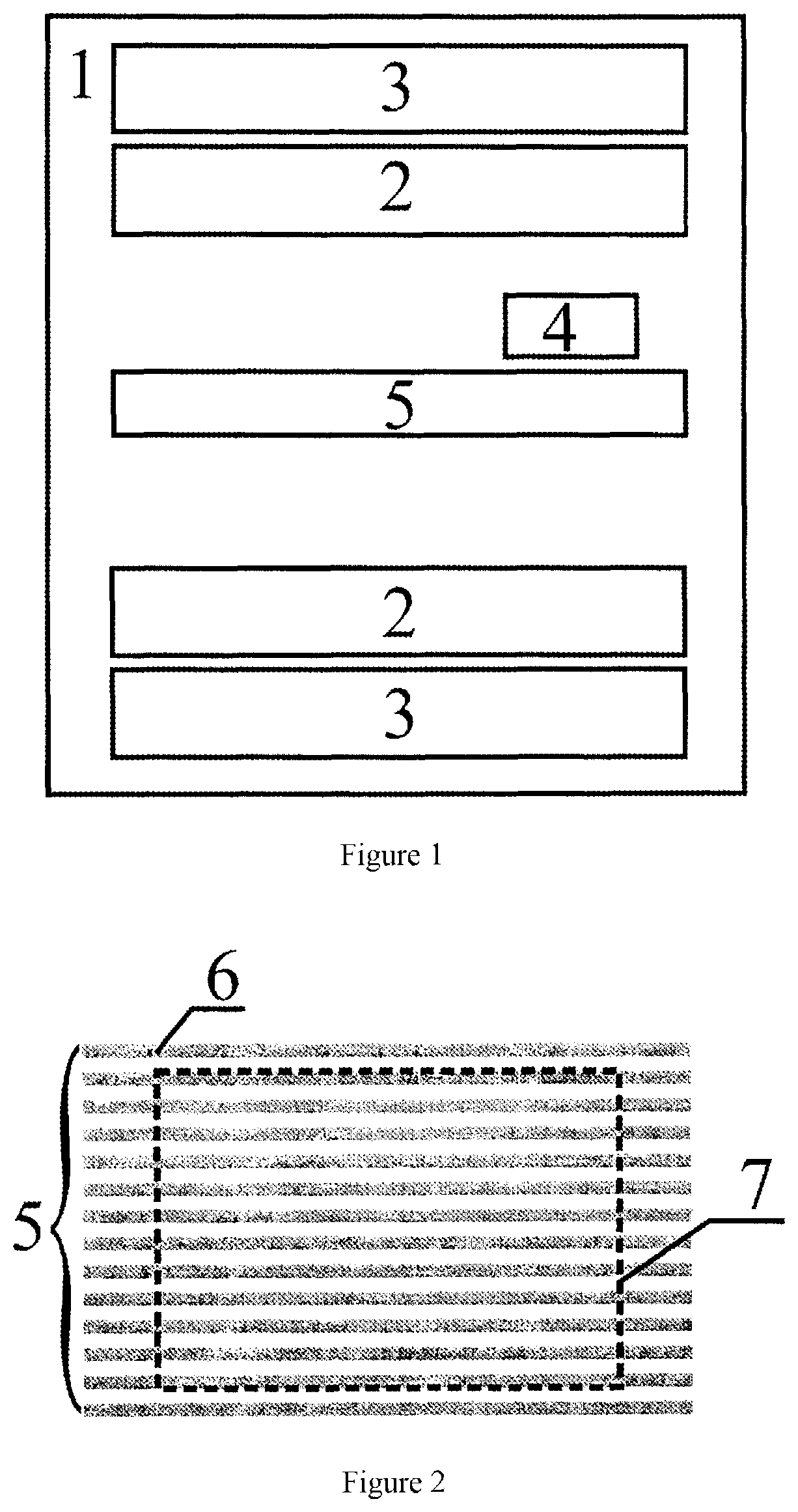
of continuous magnetic field 1 a powerful static magnetic field is created inside a magnetic resonance imaging machine, after which the subject being examined 7 is placed into the imaging machine. The magnetic moments of the protons of the subject being examined 7 align themselves parallel to the static magnetic field, the protons begin to precess at Larmor frequency, and the subject 7 acquires pronounced magnetization. Using the unit for generating a gradient magnetic field 3, additional magnetic fields are created, with said fields altering the magnitude of continuous magnetic field relative to the value, created by the source of continuous magnetic field 1, making it possible to encode the spectral and spatial response of certain lesser volumes of the subject being examined 7, said lesser volumes being characterized by their own period and frequency of Larmor precession. Then the subject being examined 7 is irradiated with an RF impulse created by the generator of radio-frequency...


PUM


Abstract

The invention relates to medical diagnostics and can be used in magnetic resonance imaging and magnetic resonance spectroscopy for increasing the quality of diagnostics of the internal organs of humans and animals. By virtue of a metamaterial, which is used as an electromagnetic field amplifier, being made from a set of advantageously oriented conductors, it becomes possible to spatially rearrange magnetic and electric fields operated at radio frequencies. In particular, in the examined object area, the radio frequency magnetic field is resonantly amplified, which makes it possible to increase the signal / noise ratio in MRI and to obtain better quality images and / or to perform the MRI examinations more quickly as there is no need to accumulate the signal. The proposed design of the metamaterial makes it possible to distance the radio frequency electric field from the area where the examined object is located, therefore enhancing safety of MRI scanning.

Description

CROSS-REFERENCE TO RELATED APPLICATIONS[0001]This application is a national stage application under 35 U.S.C. § 371 of International Application No. PCT / RU2015 / 000746, filed Nov. 6, 2015, which claims priority to Russian Patent Application No. 2015126987, filed Jul. 3, 2015, the disclosures of which are explicitly incorporated by reference herein.TECHNICAL FIELD[0002]This invention relates to the field of medical diagnostic screening and can be used in magnetic resonance imaging (MRI) and magnetic resonance spectroscopy (MRS) in order to improve the quality of diagnostic screening of human and animal internal organs.PRIOR ART[0003]MRI is currently one of the most informative methods for examining the internal organs of a human. The quality of an MR image and the size of the area of the patient which is being screened depend on the magnitude of induction of the magnetic field into which the patient is placed, and is also characterized by the magnitude of the signal-to-noise ratio, wh...

Claims


Application Information

Patent Timeline
Patent Type & Authority Patents(United States)
IPC IPC(8): G01R33/36H01Q15/00A61B5/055G01R33/34
CPCA61B5/055G01R33/34092G01R33/36H01Q15/00
Inventor SLOBOZHANYUK, ALEXEY PETROVICHPODDUBNYJ, ALEKSANDR NIKITICHBELOV, PAVEL ALEKSANDROVICH
Owner FEDERALNOE GOSUDARSTVENNOE AVTONOMNOE OBRAZOVATELNOE UCHREZHDENIE VYSSHEGO OBRAZOVANIJA SANKT PETERBURGSKIJ NATSIONALNYJ ISSLEDOVATELSKIJ UNIV INFORMATSIONNYKH TEKHNOLOGIJ MEKHANIKI I OPTIKI UNIV ITMO
Why Eureka
Try Eureka