Magnetometer and magnetometer detection method

A technology of magnetometer and laser beam, which is applied to the use of magneto-optical equipment for magnetic field measurement, the size/direction of the magnetic field, and the direction of instruments, etc., which can solve the problems of inaccurate measurement of magnetic field, measurement of magnetic field deviation, and low measurement accuracy. Magnetic sensitivity and the effect of miniaturization

Pending Publication Date: 2021-11-30
北京量子信息科学研究院
View PDF0 Cites 1 Cited by
  • Summary
  • Abstract
  • Description
  • Claims
  • Application Information

AI Technical Summary

Problems solved by technology

There will be crosstalk between the RF coils, which will introduce errors and lead to low sensitivity of the magnetometer
In addition, the angle between the radio frequency coil and the pump light in the traditional magnetometer needs to be precisely maintained at 45°, and the deviation of the angle will also lead to the deviation of the measured magnetic field.
There are two dead zones in the traditional magnetometer, and it is impossible to detect the magnetic field in the polar region parallel to the light path and the equator region perpendicular to the light
Therefore, the traditional magnetometer is inaccurate in measuring the magnetic field, and the measurement accuracy is low

Method used


Image

  • Magnetometer and magnetometer detection method
  • Magnetometer and magnetometer detection method
  • Magnetometer and magnetometer detection method

Examples


Embodiment Construction

[0029] In order to facilitate the understanding of the present application, the present application will be described more fully below with reference to the relevant drawings. Embodiments of the application are given in the drawings. However, the present application can be embodied in many different forms and is not limited to the embodiments described herein. On the contrary, the purpose of providing these embodiments is to make the disclosure of this application more thorough and comprehensive.

[0030]Unless otherwise defined, all technical and scientific terms used herein have the same meaning as commonly understood by one of ordinary skill in the technical field to which this application belongs. The terms used herein in the specification of the application are only for the purpose of describing specific embodiments, and are not intended to limit the application.

[0031] It will be understood that when an element or layer is referred to as being "on," "adjacent," "conn...


PUM


Abstract

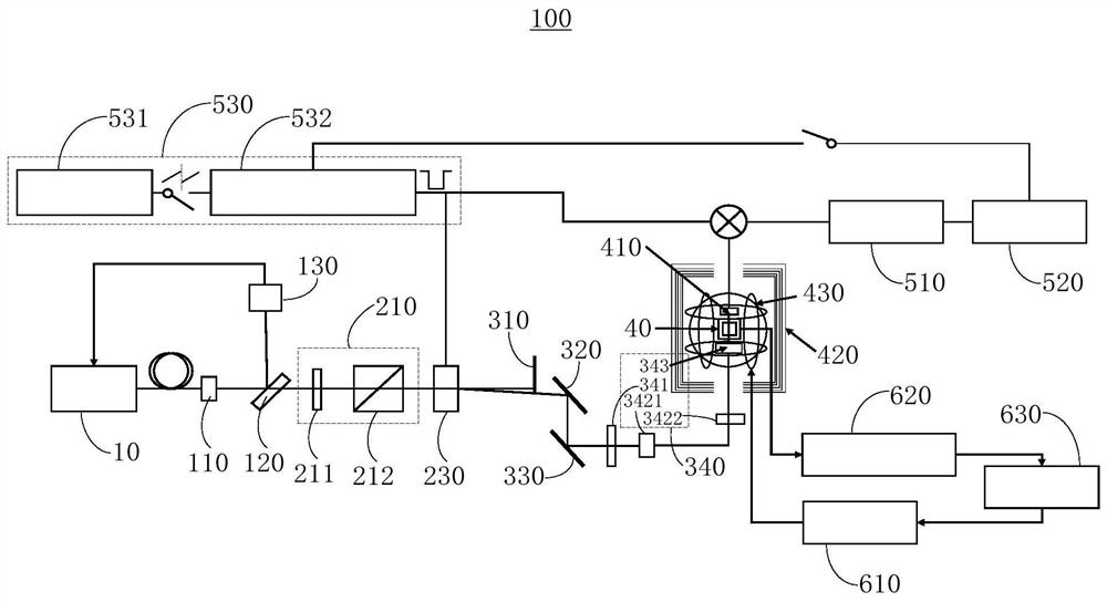
The invention relates to a magnetometer and a magnetometer detection method. A laser module is used for emitting a first laser beam. A beam splitting module is arranged on a light path of the first laser beam. A linear polarization module is arranged on a light path of the second laser beam. An acousto-optic modulation module is arranged on a light path of the linearly polarized light beam with adjustable light intensity. A diffracted light selection module is arranged on a light path of the diffracted light. A circular polarization module is arranged on a light path of the first-stage diffracted light. An atomic gas chamber is arranged on a light path of the circularly polarized light. A photoelectric detection module is arranged on a light path of the detection light. The output end of a signal generation module is connected with the control end of the acousto-optic modulation module. The input end of a lock-in amplification module is connected with the output end of the photoelectric detection module and the output end of the signal generation module. The input end of a control module is connected with the output end of the lock-in amplification module, and the output end of the control module is connected with the control end of the signal generation module.

Description

technical field [0001] The present application relates to the technical field of quantum precision measurement, in particular to a magnetometer and a magnetometer detection method. Background technique [0002] The detection of weak magnetic field signals can be applied in many important fields, such as non-destructive testing, geological exploration, underwater long-wave communication and geomagnetic navigation. The magnetic field measured by a traditional fluxgate is generally on the order of nT, and it is impossible to measure a weaker magnetic field. There are two main types of magnetometers and gradiometers developed based on quantum effects. One is the magnetometer or gradiometer developed based on superconducting quantum interference devices, and the other is the atomic magnetometer or magnetic gradiometer. The atomic magnetometer does not require a huge refrigeration device, and it is easier to realize the miniaturization of the device. At the same time, the sensiti...

Claims


Application Information

Patent Timeline
Patent Type & Authority Applications(China)
IPC IPC(8): G01R33/032G01R33/00
CPCG01R33/032G01R33/0011
Inventor 罗文浩杨仁福魏小刚张笑楠杜艺杰丛楠
Owner 北京量子信息科学研究院
Why Eureka
Try Eureka