Apparatus for actuating and controlling the rotation of blades of fans for cooling the coolant in machines/vehicles

a technology of actuator and fan blade, which is applied in the direction of engine cooling apparatus, liquid fuel engine, engine fuction, etc., to achieve the effect of preventing any residual power consumption, easy and low-cost manner

Active Publication Date: 2020-08-11
BARUFFALDI
View PDF11 Cites 1 Cited by
  • Summary
  • Abstract
  • Description
  • Claims
  • Application Information

AI Technical Summary

Benefits of technology

[0019]Preferably it is required that the fan should be able to be stopped in the so-called “fully stopped” condition where, after interruption of operation, it is kept in a completely immobile and not just idle condition, in order to prevent any residual power consumption due to residual rotation of the fan caused by friction in the kinematic chain for controlling rotation.
[0020]In connection with this problem it is also required that this apparatus should have small dimensions, in particular small radial dimensions, which make it suitable for being housed within the confined space between the heat engine and radiator inside the engine compartment of operating machines or land vehicles and should be able to be produced and assembled in an easy and low-cost manner in any operating machine / vehicle without the need for auxiliary devices and / or complicated connection lines.

Problems solved by technology

The technical problem which is posed, therefore, is that of providing an apparatus for actuating and controlling rotation, about their longitudinal axis, of the blades of fans for cooling the coolant in operating machines and / or vehicles, in particular vehicles such as agricultural tractors and off-road vehicles, which is able to perform both effective cooling of the coolant during normal use of the machine / vehicle and cleaning of the radiator cells should they become blocked.

Method used


Image

  • Apparatus for actuating and controlling the rotation of blades of fans for cooling the coolant in machines/vehicles
  • Apparatus for actuating and controlling the rotation of blades of fans for cooling the coolant in machines/vehicles
  • Apparatus for actuating and controlling the rotation of blades of fans for cooling the coolant in machines/vehicles

Examples


Embodiment Construction

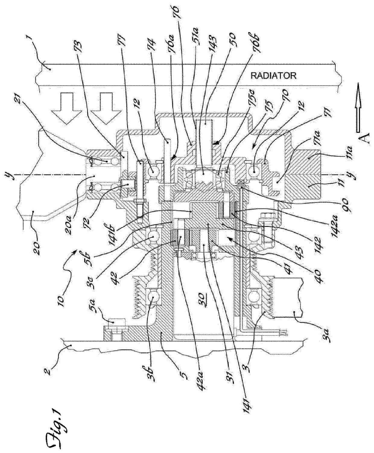
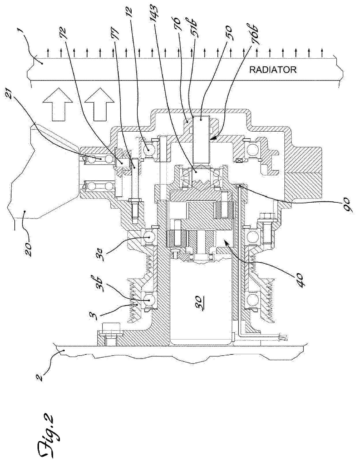
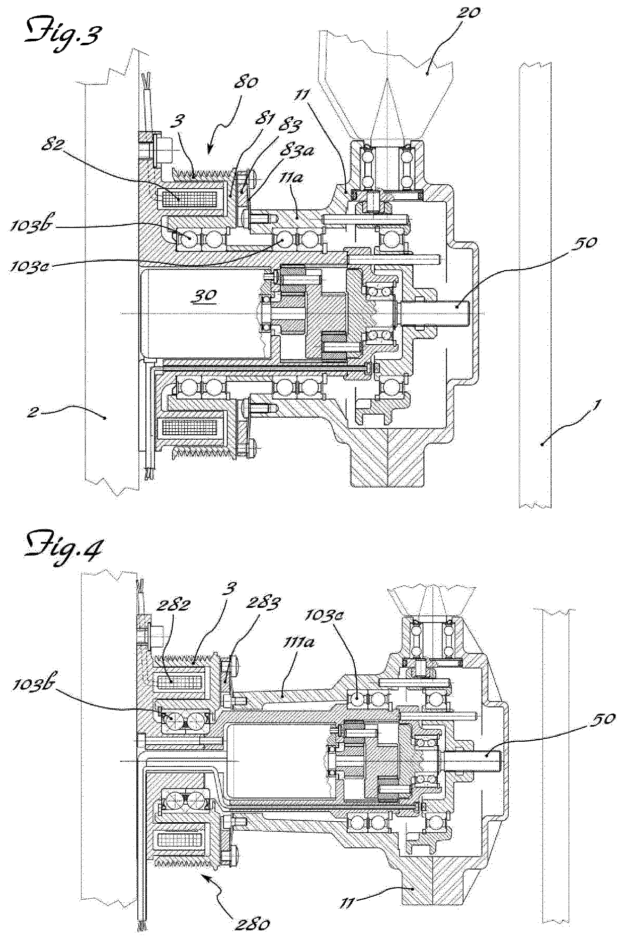
[0031]As shown in FIG. 1 and assuming solely for the sake of easier description and without a limiting meaning a longitudinal axis X-X corresponding to the axis of rotation of a fan 10 and, with reference to the direction of travel of a vehicle indicated by the arrow “A”, a front part corresponding to the position of a radiator 1 and a rear part corresponding to the position of the heat engine 2, the fan 10 is arranged behind the radiator 1 and in front of the engine 2 and comprises a hub 11 which is preferably closed at the front by a bell member 11a.

[0032]The hub 11 is axially locked to a pulley 3 for rotationaly driving the fan and connected by means of a suitably driven belt 3a to the shaft of heat engine 2.

[0033]The pulley 3 is mounted on a pair of bearings 3b,3c which are keyed onto a fixed support element, in the example described consisting of a sleeve 5 which is fixed to the base of the engine 2 via associated means 5a and inside which the apparatus for controlling rotatio...


PUM


Abstract

Apparatus for actuating and controlling the rotation, about their longitudinal axis (Y-Y), of blades (20) of cooling fans (10) for operating machines and / or vehicles, in particular agricultural tractors and off-road vehicles, said fan being mounted on a hub (11) which can be rotationally driven about its axis (X-X) by associated driving means (3,3a) suitable for connection to the heat engine (1) and mounted on a fixed support (5) by means of a bearing (3b) the apparatus comprising a ring (71) provided with a radial seat (71a) inside which a radial pin (72), eccentrically engaged in a base (73) integral with the shank (20a) of the blade (20), is inserted; an electric motor (30) which is coaxial with the axis (X-X) of the hub (11) and the shaft (31) of which is coaxially connected to a reduction gear (40), the kinematic output element (143) of which is coaxially connected by means of a screw (51a) / female thread (76a) coupling to a slider (76) displaceable in both directions along the axis (X-X) and kinematically connected to the ring (71) with an eccentric pin (72) driving the base (73) of the shank of the blade, an electromagnetic clutch (80; 180; 280) being arranged between the pulley (3) and the hub (11) of the fan.

Description

BACKGROUND OF THE INVENTIONField of the Invention[0001]The present invention relates to an apparatus for actuating and controlling the rotation, about their axis, of the blades of fans for cooling the coolant contained in the radiator of operating machines and / or vehicles, in particular agricultural tractors and off-road vehicles.[0002]It is known that the operation of operating machines and vehicles by means of a heat engine involves the need to cool the latter by means of a coolant which is stored inside a cellular radiator and recirculated through the engine; the coolant is in turn cooled by the ambient air which is forced to pass through the radiator by the sucking action of a rotating fan.[0003]Taking as a reference point the normal front part of the machine / vehicle the three elements are axially arranged with the radiator at the front, engine behind and fan arranged between the two.[0004]It is also known that, in the technical sector of vehicles which are generally used in con...

Claims


Application Information

Patent Timeline
Patent Type & Authority Patents(United States)
IPC IPC(8): F04D29/32F04D19/00F04D29/36F01P7/08F01P7/06
CPCF01P7/06F01P7/084F04D29/362F04D19/002F04D29/323F05D2260/76F05D2260/74
Inventor BOFFELLI, PIERCARLO
Owner BARUFFALDI
Why Eureka
Try Eureka