
Sealed retractable fall arrest block

a technology of a retractable block and a seal is applied in the field of sealable component fall arrest units, which can solve the problems of mechanical difficulty, periodically inspected, and costing and time-consuming, and achieve the effects of convenient replacement of worn, damaged or non-functional parts, and convenient access

Active Publication Date: 2020-08-18
RELIANCE INDUSTRIES LIMITED
View PDF26 Cites 5 Cited by
  • Summary
  • Abstract
  • Description
  • Claims
  • Application Information

AI Technical Summary

Benefits of technology

The retractable fall arrest unit described in the patent is designed to have a durable and reliable structure that can safely withstand high levels of use. The components are lightweight and easy to replace, reducing downtime and costs. The seals prevent contaminants from entering the critical parts, and the use of sacrificial anodes further protects against corrosion. The retractable is designed for use in hazardous environments and meets industry standards for safety and reliability.

Problems solved by technology

One of the difficulties of using mechanical retractable shock absorbing lifelines is that they must be periodically inspected for damage and be retested to confirm that they are operating correctly.
The reason these units must be returned to the manufacturer is because they are mechanically difficult to service due to the precision setting required on the clutch assembly and the difficulty of unloading and removing the power retraction springs, which may be over 100 ft. long.
This is both costly and time consuming, requiring the customer to purchase extra units that can be rotated out of service for recertification on a regular schedule.
These problems are greatly compounded when retractable units are used in off-shore work sites where the retractables will be exposed to a salt (and thus, corrosive) atmosphere.
Further, when a retractable is being serviced, it is out of commission for about two months.

Method used


Image

  • Sealed retractable fall arrest block
  • Sealed retractable fall arrest block
  • Sealed retractable fall arrest block

Examples


Embodiment Construction

[0079]The following detailed description illustrates the claimed invention by way of example and not by way of limitation. This description will clearly enable one skilled in the art to make and use the claimed invention, and describes several embodiments, adaptations, variations, alternatives and uses of the claimed invention, including what is presently believed to be the best mode of carrying out the claimed invention. Additionally, it is to be understood that the claimed invention is not limited in its application to the details of construction and the arrangements of components set forth in the following description or illustrated in the drawings. The claimed invention is capable of other embodiments and of being practiced or being carried out in various ways. Also, it is to be understood that the phraseology and terminology used herein is for the purpose of description and should not be regarded as limiting.

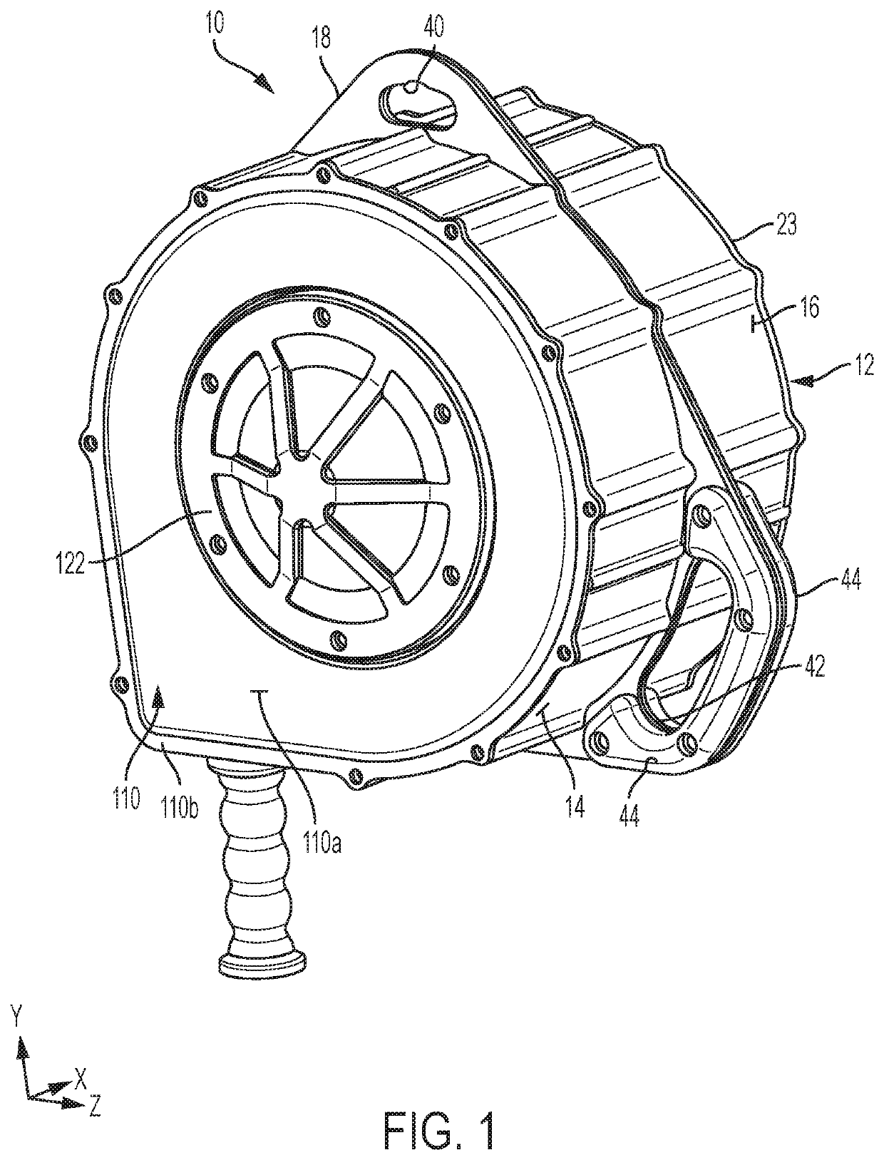
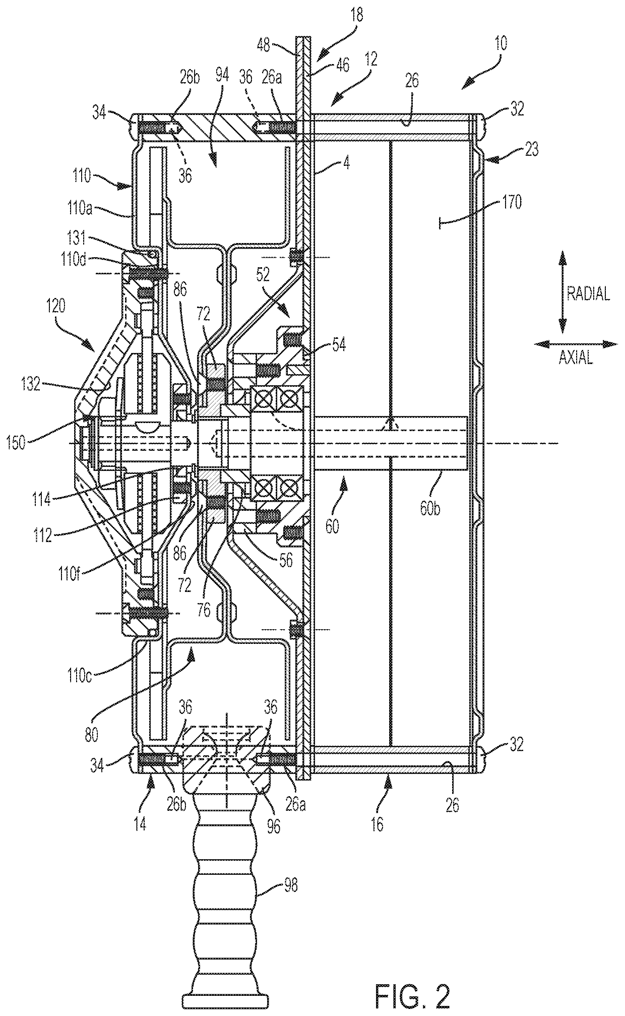
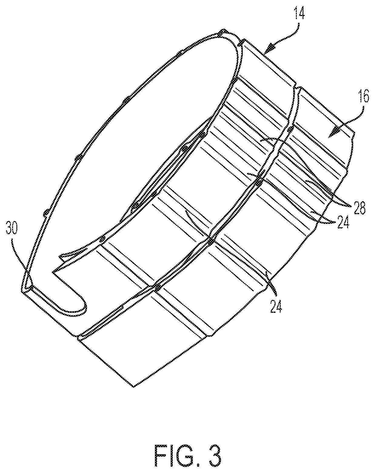
[0080]A sealed retractable fall arrest unit or block 10 (“block” or “s...


PUM


Abstract

A retractable fall arrest block comprising a spring side housing member and a drum side housing member. A center support wall, defining a bearing housing, is secured between the housing members. A bearing assembly is mounted in the bearing housing to support a spindle. A spring side housing member is mounted to a spring side of the center support wall and a spring side cover is mounted to the spring side housing member opposite the center support wall to define a spring housing. A drum side housing member is mounted to a drum side of the center support wall, and a drum side cover is mounted to the drum side housing member to define a drum housing. The spindle extends into both housings. A spring is mounted in the spring housing. A drum is positionally fixed to the spindle in the drum housing. A clutch assembly is mounted to the spindle to stop the drum from unwinding.

Description

CROSS-REFERENCE TO RELATED APPLICATIONS[0001]This application is the National Stage under 35 U.S.C. § 371 of International App. No. PCT / US2016 / 034249 which claims priority to U.S. App. No. 62 / 170,461 filed Jun. 3, 2015 which is entitled “Sealed Retractable Fall Arrest Block” and both of which are incorporated herein by reference.STATEMENT REGARDING FEDERALLY SPONSORED RESEARCH OR DEVELOPMENT[0002]Not Applicable.BACKGROUND OF THE INVENTION[0003]This application relates to fall arrest units, and, in particular to sealed component fall arrest units in which all the rotating components (i.e., return spring, drum, and clutch) are supported by a cantilevered main shaft or spindle rotatably mounted in the housing of the fall arrest unit so as to prevent the housing itself from bearing any substantial load. Further, the construction of the fall arrest unit allows for the entire working assembly to be easily accessed to facilitate replacement of worn, damaged, or non-functioning parts.[0004]...

Claims


Application Information

Patent Timeline
Patent Type & Authority Patents(United States)
IPC IPC(8): A62B35/04A62B35/00
CPCA62B35/04A62B35/0093
Inventor CHOATE, GARY E.HENN, DAN
Owner RELIANCE INDUSTRIES LIMITED
Learn More