
Device for locking workpieces on machine tools

a technology for locking workpieces and machine tools, which is applied in the direction of clamps, manufacturing tools, etc., can solve the problems of excessive deformation of workpieces, damage and consequently being discarded, and the workpiece itself may interfere with the brack

Active Publication Date: 2020-08-25
HYDROBLOCK
View PDF7 Cites 1 Cited by
  • Summary
  • Abstract
  • Description
  • Claims
  • Application Information

AI Technical Summary

Benefits of technology

[0039]The main aim of the present invention is to provide a device for locking workpieces on machine tools that enables the achievement of the above mentioned improvements and allows to stably lock a workpiece to be machined on a machine tool without charging it in any way from the tensional point of view and without deforming it.
[0040]Another object of the present invention is to provide a device for locking workpieces on machine tools which allows to overcome the mentioned drawbacks of the prior art within the ambit of a simple, rational, easy and effective to use as well as affordable solution.

Problems solved by technology

Pressure values of this magnitude cause the sealing gaskets to compress, which significantly increases the friction forces involved, with the result that the force exerted by the bracket and / or counter-bracket on the workpiece to be machined can be not negligible and cause excessive deformation of the workpiece (especially when it comes to thin pieces, which do not have an intrinsic strength), so as to discard the machined workpiece because it does not meet the required tolerances.
Another drawback is due to the fact that the helical spring contained in the hollow rod loses its initial characteristics of elasticity over time; therefore a periodical maintenance should be scheduled for the replacement of the spring, to avoid a reduction of the maximum opening (home position) between bracket and counter-bracket, with the risk that when the workpiece, after its machining, is removed by the robot, the workpiece itself may interfere with the bracket, be damaged and consequently being discarded.
Still a further drawback is due to the fact that the device described above is single-acting, i.e. that the aforementioned second chamber is in communication with the outside.
This communication can generate corrosion phenomena, as well as dirt and / or particles being present at the entrance of this chamber produced by the machining of the workpiece, which can alter the operation of the device.

Method used


Image

  • Device for locking workpieces on machine tools
  • Device for locking workpieces on machine tools
  • Device for locking workpieces on machine tools

Examples


Embodiment Construction

[0039]The main aim of the present invention is to provide a device for locking workpieces on machine tools that enables the achievement of the above mentioned improvements and allows to stably lock a workpiece to be machined on a machine tool without charging it in any way from the tensional point of view and without deforming it.

[0040]Another object of the present invention is to provide a device for locking workpieces on machine tools which allows to overcome the mentioned drawbacks of the prior art within the ambit of a simple, rational, easy and effective to use as well as affordable solution.

[0041]The above mentioned objects are achieved by the present device for locking workpieces on machine tools having the characteristics of claim 1.

BRIEF DESCRIPTION OF THE DRAWINGS

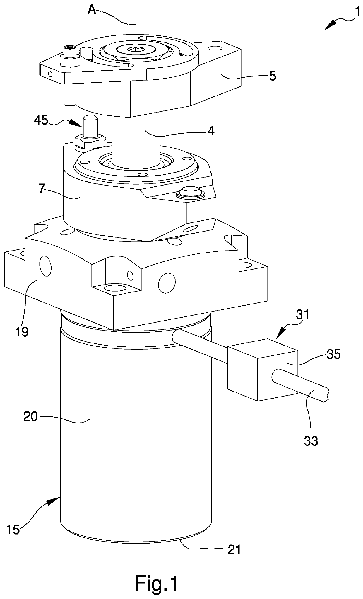
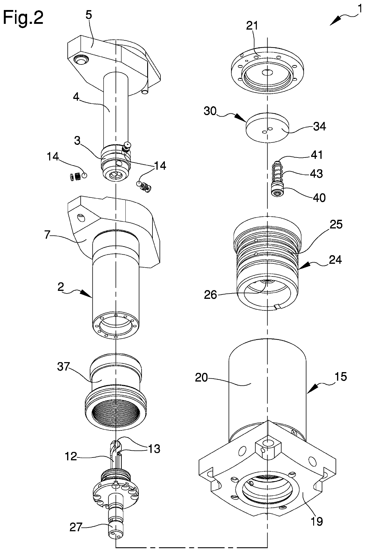
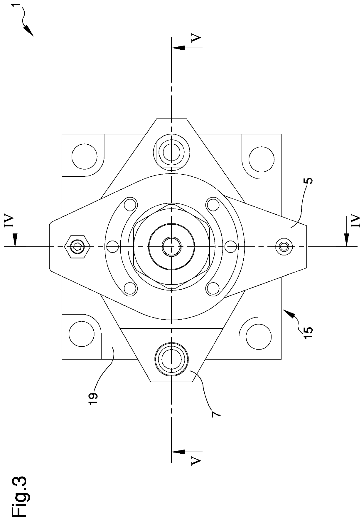
[0042]Other characteristics and advantages of the present invention will become more evident from the description of a preferred, but not exclusive, embodiment of a device for locking workpieces on machine tools, ...


PUM


Abstract

The device (1) for locking workpieces on machine tools comprises: —a first hydraulic cylinder (2) inside which at least one piston (3, 4) is inserted slidably along a main line (A); —a second hydraulic cylinder (15) inside which the first hydraulic cylinder (2) is inserted slidably along the main line (A), the feeding of a pressurised hydraulic fluid into a first chamber (8) being designed to apply to the first hydraulic cylinder (2) a primary force (F) that shifts the first hydraulic cylinder (2) from a home position to a second operating position; —an auxiliary chamber (28) provided between the first hydraulic cylinder (2) and the second hydraulic cylinder (15) and associated with pneumatic feeding means (29, 30, 31) designed to feed pressurised air into the auxiliary chamber (28), the feeding of the pressurised air applying to the first hydraulic cylinder (2) an auxiliary force (Fa) along the main line (A) in the same direction as and operating in conjunction with the primary force (F).

Description

TECHNICAL FIELD[0001]The present invention relates to a device for locking workpieces on machine tools.BACKGROUND ART[0002]As is known, in the mass production of mechanical workpieces that require machining to the machine tool, a robot brings the workpieces to be machined to a machine tool, where suitable means, of the hydraulic type, take over the workpiece and lock it in position to allow the machining thereof.[0003]When machining has finished the aforementioned means release the machined workpiece, which is once again moved away by the robot.[0004]One type of hydraulic means used for this purpose comprises a hydraulic device consisting essentially of a first cylinder in which a hollow piston is slidably inserted comprising a head and a coaxial rod the distal end of which projects from the cylinder.[0005]The cavity in the piston is open only on the side of the piston head.[0006]In this cavity a helical spring is inserted, one end of which rests at the closed end of the rod while t...

Claims


Application Information

Patent Timeline
Patent Type & Authority Patents(United States)
IPC IPC(8): B25B5/12B25B5/06
CPCB25B5/062
Inventor ZANNI, DAVIDE
Owner HYDROBLOCK
Learn More