Eureka AIR delivers breakthrough ideas for toughest innovation challenges, trusted by R&D personnel around the world.

Method for operating an electro hydraulic brake system, and brake system

a technology of electrohydraulic brakes and brake systems, applied in brake systems, brake components, vehicle sub-unit features, etc., can solve the problems of inability to control the system, superposed brake actuation by the human driver during, and the possibility of braking action is limited to approximately 60%

Active Publication Date: 2020-08-25
CONTINENTAL TEVES AG & CO OHG
View PDF18 Cites 2 Cited by
  • Summary
  • Abstract
  • Description
  • Claims
  • Application Information

AI Technical Summary

Benefits of technology

[0022]In a preferred embodiment of an aspect of the invention, for the brake pressure build-up in the second and the fourth wheel brake by means of the second pressure provision device, at least one of the valves of the first brake system is actuated. Since electrically actuatable components of the first and of the second brake system are actuated, this operating method is also referred to as a cooperative operating concept of first and second brake system. The cooperative operating concept permits an improved overall braking action, prevents or reduces yaw disturbances of the vehicle during the braking operation, and permits the control of the brake installation in the event of a superposed brake actuation by the human driver.
[0034]The first and second brake systems are preferably formed as separate modules (units) or as separate electrohydraulic open-loop and closed-loop control units, which each comprise a hydraulics unit (or hydraulic open-loop and closed-loop control unit) and an electronics unit (or electronic open-loop and closed-loop control unit). It is however also possible for the first and the second brake system, in particular the hydraulic components thereof, to be arranged in one unit or one module (for example in one housing or in one hydraulics unit / hydraulic open-loop and closed-loop control unit). Then, too, it is advantageous if each of the brake systems is assigned a separate electronics unit or electronic open-loop and closed-loop control unit for the activation of the corresponding pressure provision device and valves of the respective brake system.
[0040]The second brake system preferably comprises at least one second pressure medium reservoir, which is in particular at atmospheric pressure and from which the second pressure provision device can draw pressure medium. The second pressure medium reservoir is particularly preferably integrated into the hydraulics unit of the second brake system. In this way, it is possible to avoid insufficient pressure medium being available when required owing to a leaking or destroyed hydraulic line to a pressure medium reservoir assigned to the first brake system.
[0048]It is advantageous if an intake valve which is closed when electrically deenergized is connected into each of the suction lines.
[0050]A first hydraulic return line branches off from the hydraulic connection between the first brake system and the first wheel brake in a region between the isolating valve and the first wheel brake, which first hydraulic return line is hydraulically connected to the associated second pressure medium reservoir. Correspondingly, a second hydraulic return line branches off from the hydraulic connection between the first brake system and the third wheel brake in a region between the corresponding isolating valve and the third wheel brake, which second hydraulic return line is hydraulically connected to the other second pressure medium reservoir. In this way, pressure medium can be discharged from the corresponding wheel brake in a targeted manner. This permits the setting of different brake pressures in the first and the third, wheel brake, which are hydraulically connected directly to the second brake system.

Problems solved by technology

For example, a superposed brake actuation by the human driver during the provision of pressure by the secondary brake system, that is to say a takeover by the driver, cannot be performed in a manner controlled by the system.
Also, during the provision of pressure by the secondary brake system only to two of the four wheel brakes, the possible braking action is limited to approximately 60%.

Method used


Image

  • Method for operating an electro hydraulic brake system, and brake system
  • Method for operating an electro hydraulic brake system, and brake system
  • Method for operating an electro hydraulic brake system, and brake system

Examples


Embodiment Construction

[0063]In all of the figures, identical parts are denoted by the same reference designations.

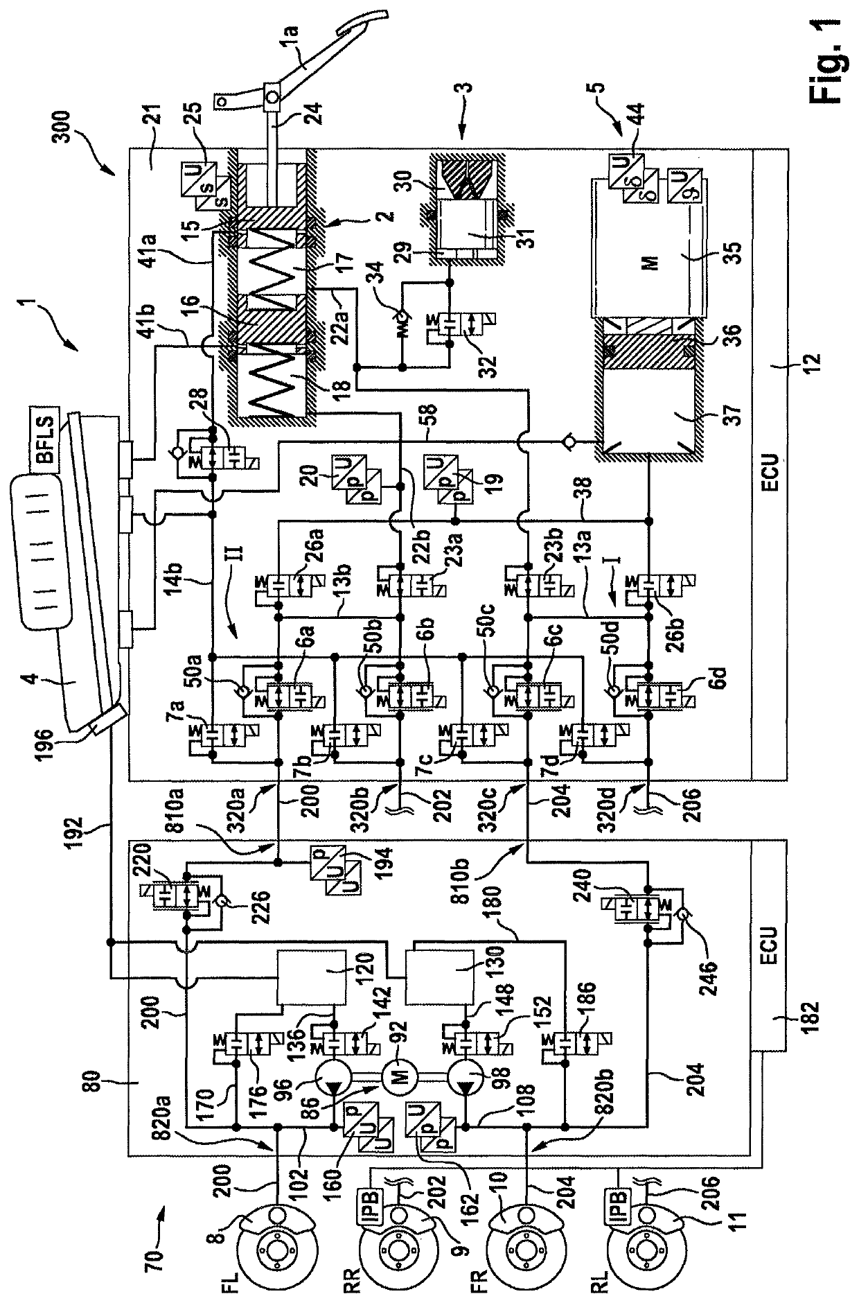
[0064]FIG. 1 illustrates an exemplary brake installation 1 for implementing a method according to an aspect of the invention. The brake installation comprises a first brake system (primary brake system) 300, a second brake system (secondary brake system) 70 and four hydraulically actuatable wheel brakes 8-11. An expansion to more than four wheel brakes is easily possible.

[0065]In an example, the first brake system 300 and the second brake system 70 are each formed as a separate module (electrohydraulic open-loop and closed-loop control unit HECU). It is however also possible for the primary brake system 300 and secondary brake system 70 to be arranged in one unit / one module (for example in one housing). In the example, the electrohydraulic open-loop and closed-loop control unit of the first brake system comprises a hydraulics unit (or hydraulic open-loop and closed-loop control unit) 21 and a...


PUM


Abstract

A method for operating an electrohydraulic brake installation for a motor vehicle having at least first, second, third and fourth hydraulically actuatable wheel brakes, a first brake system including a master brake cylinder actuatable by a brake pedal and hydraulically connected by at least one electrically actuatable isolating valve to the four wheel brakes, and including a first electrically controllable pressure provision device hydraulically connected to the four wheel brakes via at least one electrically actuatable sequence valve, and a second brake system including a second electrically controllable pressure provision device hydraulically connected to the first and the third wheel brake, and including in each case one isolating valve for the first and third wheel brake. The isolating valve is arranged in each case in a hydraulic connection between the first brake system and the corresponding wheel brake.

Description

CROSS REFERENCE TO RELATED APPLICATIONS[0001]This application is the U.S. National Phase Application of PCT International Application No. PCT / EP2017 / 075632, filed Oct. 9, 2017, which claims priority to German Patent Application No. 10 2016 219 699.5, filed Oct. 11, 2016, and German Patent Application No. 10 2017 216 118.3, filed Sep. 13, 2017 the contents of such applications being incorporated by reference herein.FIELD OF THE INVENTION[0002]The invention relates to a method for operating an electrohydraulic brake installation, and to a brake installation in which such a method is implemented.BACKGROUND OF THE INVENTION[0003]In motor vehicle engineering, “brake-by-wire” brake installations are being used ever more widely. Such brake installations comprise not only a master brake cylinder which is actuatable by the vehicle driver but also an electrically activatable pressure provision device, by means of which an actuation of the wheel brakes is performed in a “brake-by-wire” operati...

Claims


Application Information

Patent Timeline
Patent Type & Authority Patents(United States)
IPC IPC(8): B60T13/58B60T13/68B60T8/40B60T13/16B60T13/66
CPCB60T8/4081B60T13/165B60T13/686B60T13/161B60T13/662B60T2270/404B60T2270/402B60Y2400/81
Inventor PEICHL, THOMASSCHMIDT, HOLGERULLRICH, THORSTEN
Owner CONTINENTAL TEVES AG & CO OHG
Why Eureka
Eureka Blog
Learn More