Eureka AIR delivers breakthrough ideas for toughest innovation challenges, trusted by R&D personnel around the world.

Method for operating an electro hydraulic brake system, and brake system

Active Publication Date: 2019-08-08
CONTINENTAL TEVES AG & CO OHG
View PDF7 Cites 3 Cited by
  • Summary
  • Abstract
  • Description
  • Claims
  • Application Information

AI Technical Summary

Benefits of technology

This patent describes a system for controlling braking in a vehicle. The system uses two separate brake systems, one for the front wheels and one for the rear wheels. By combining the use of electric actuators in both systems, the overall braking action is improved, and the systems work together to prevent yaw disturbances and control the brakes in case of a superposed brake actuation by the driver. The brake systems can be separate modules or integrated into one hydraulics unit. The system also includes pressure medium reservoirs for each brake system, as well as intake valves to prevent insufficient pressure medium. Different brake pressures can be set in the front and rear wheels by targeted discharge of pressure medium from the corresponding wheel brake.

Problems solved by technology

For example, a superposed brake actuation by the human driver during the provision of pressure by the secondary brake system, that is to say a takeover by the driver, cannot be performed in a manner controlled by the system.
Also, during the provision of pressure by the secondary brake system only to two of the four wheel brakes, the possible braking action is limited to approximately 60%.

Method used


Image

  • Method for operating an electro hydraulic brake system, and brake system
  • Method for operating an electro hydraulic brake system, and brake system
  • Method for operating an electro hydraulic brake system, and brake system

Examples


Embodiment Construction

[0063]In all of the figures, identical parts are denoted by the same reference designations.

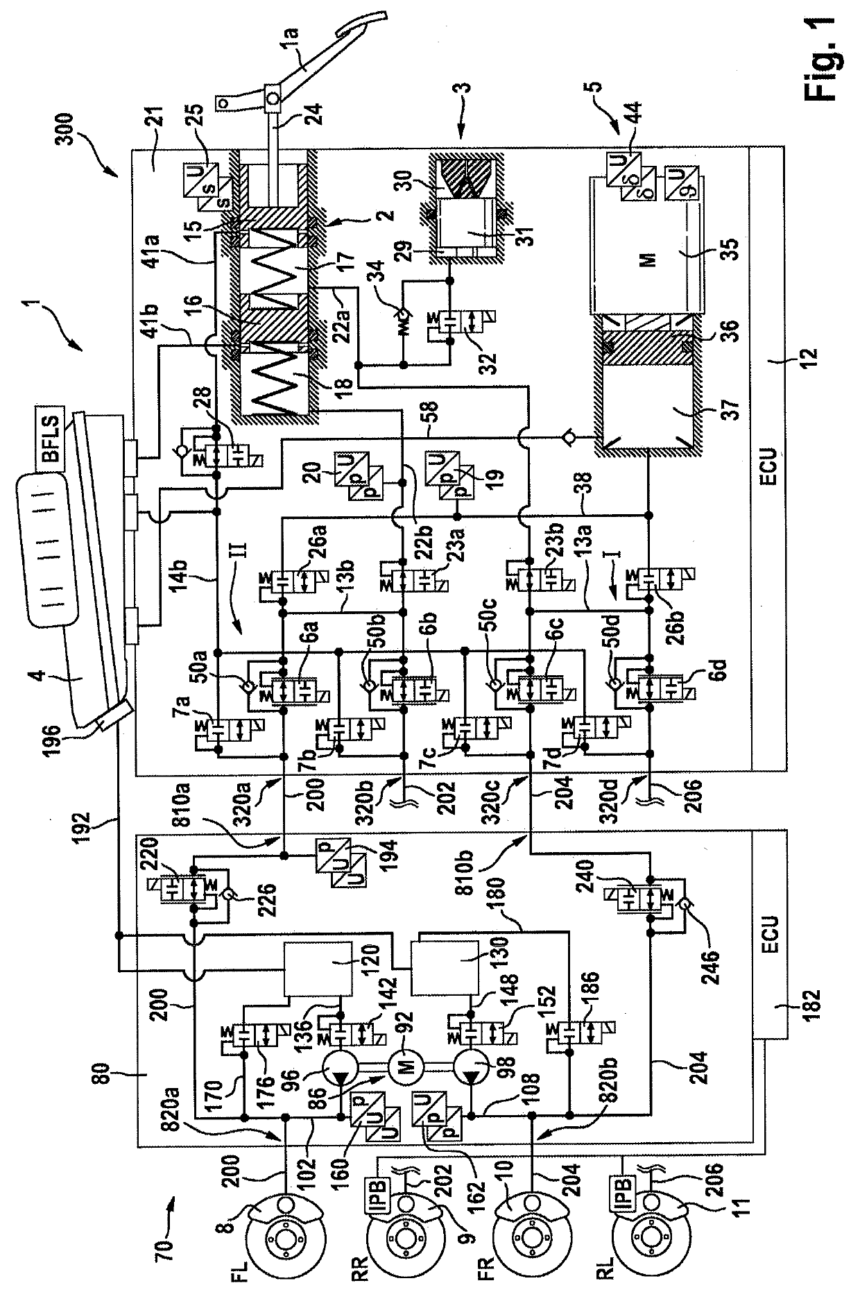
[0064]FIG. 1 illustrates an exemplary brake installation 1 for implementing a method according to an aspect of the invention. The brake installation comprises a first brake system (primary brake system) 300, a second brake system (secondary brake system) 70 and four hydraulically actuatable wheel brakes 8-11. An expansion to more than four wheel brakes is easily possible.

[0065]In an example, the first brake system 300 and the second brake system 70 are each formed as a separate module (electrohydraulic open-loop and closed-loop control unit HECU). It is however also possible for the primary brake system 300 and secondary brake system 70 to be arranged in one unit / one module (for example in one housing). In the example, the electrohydraulic open-loop and closed-loop control unit of the first brake system comprises a hydraulics unit (or hydraulic open-loop and closed-loop control unit) 21 and a...


PUM


Abstract

A method for operating an electrohydraulic brake installation for a motor vehicle having at least first, second, third and fourth hydraulically actuatable wheel brakes, a first brake system including a master brake cylinder actuatable by a brake pedal and hydraulically connected by at least one electrically actuatable isolating valve to the four wheel brakes, and including a first electrically controllable pressure provision device hydraulically connected to the four wheel brakes via at least one electrically actuatable sequence valve, and a second brake system including a second electrically controllable pressure provision device hydraulically connected to the first and the third wheel brake, and including in each case one isolating valve for the first and third wheel brake. The isolating valve is arranged in each case in a hydraulic connection between the first brake system and the corresponding wheel brake.

Description

CROSS REFERENCE TO RELATED APPLICATIONS[0001]This application is the U.S. National Phase Application of PCT International Application No. PCT / EP2017 / 075632, filed Oct. 9, 2017, which claims priority to German Patent Application No. 10 2016 219 699.5, filed Oct. 11, 2016, and German Patent Application No. 10 2017 216 118.3, filed Sep. 13, 2017 the contents of such applications being incorporated by reference herein.FIELD OF THE INVENTION[0002]The invention relates to a method for operating an electrohydraulic brake installation, and to a brake installation in which such a method is implemented.BACKGROUND OF THE INVENTION[0003]In motor vehicle engineering, “brake-by-wire” brake installations are being used ever more widely. Such brake installations comprise not only a master brake cylinder which is actuatable by the vehicle driver but also an electrically activatable pressure provision device, by means of which an actuation of the wheel brakes is performed in a “brake-by-wire” operati...

Claims


Application Information

Patent Timeline
IPC IPC(8): B60T13/68B60T13/16B60T8/40
CPCB60T13/686B60T13/161B60T8/4081B60T2270/402B60T2270/404B60T13/165B60T13/662B60Y2400/81
Inventor PEICHL, THOMASSCHMIDT, HOLGERULLRICH, THORSTEN
Owner CONTINENTAL TEVES AG & CO OHG
Why Eureka
Eureka Blog
Learn More