Aircraft wing with aileron

a technology of aircraft wings and ailerons, applied in the field of aircraft wings, can solve the problems of reducing the effectiveness of ailerons and effectively limited maximum aircraft spans

Active Publication Date: 2020-08-25
AIRBUS OPERATIONS LTD
View PDF17 Cites 2 Cited by
  • Summary
  • Abstract
  • Description
  • Claims
  • Application Information

AI Technical Summary

Benefits of technology

[0011]The fixed wing may comprise one or more actuators associated with the master flight control surface. The one or more actuators may control the movement of the master flight control surface. The interface between the master flight control surface and the slave flight control surface, when the wing tip device is in the flight configuration, may be arranged such that movement of the master flight control surface drives movement of the slave flight control surface. In such an arrangement, there is no need to provide independent actuation of the slave flight control surface. This may simplify the construction of the wing.
[0014]The orientation of the rotation axis is preferably such that when the wing tip device is rotated about the axis, from the flight configuration to the ground configuration, the span of the aircraft wing is reduced.
[0016]The interface between the master flight control surface and slave flight control surface may be located in the same plane as the oblique cut plane. The interface may be configured such that rotation of the wing tip device between the flight configuration and ground configuration, such that the wing tip device rotates around an axis perpendicular to the oblique cut plane, may de-couple the interface. Rotation of the wing tip device between the ground configuration and the flight configuration may couple the interface between the wing tip device and the fixed wing. The flight control axis, around which the master flight control surface and slave flight control surface may be rotated when the wing tip device is in the flight configuration, and the rotation axis of the wing tip device, may be arranged to be neither coaxial nor parallel. That the rotational axis and the flight control axis are in different directions allows there to be a rigid connection between the wing tip device and fixed wing with respect to movement in a first direction (around the flight control axis), and also allows de-coupling of the interface between the wing tip device and fixed wing in a second direction (the rotational axis).

Problems solved by technology

However, the maximum aircraft span is effectively limited by airport operating rules which govern various clearances required when maneuvering around the airport (such as the span and / or ground clearance required for gate entry and safe taxiway usage).
However, the use of such wing tip devices has meant that ailerons, which are typically located towards the end of a wing, have to be moved inboard on the wing, or reduced in length, as the presence of a junction between the movable wing tip device and fixed wing means conventional ailerons would not be operable.
This reduces the effectiveness of the ailerons.

Method used


Image

  • Aircraft wing with aileron
  • Aircraft wing with aileron
  • Aircraft wing with aileron

Examples


Embodiment Construction

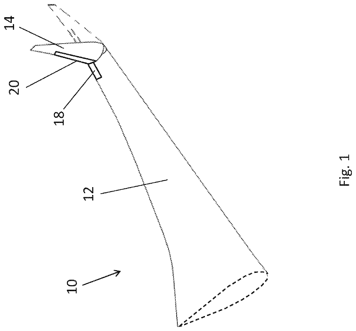
[0040]FIG. 1 shows an aircraft wing 10 comprising a fixed wing 12, connected to the fuselage of an aircraft (not shown in FIG. 1) and a movable wing tip device 14. The movable wing tip device 14 is movable between a flight configuration, as shown by the broken lines, and a ground configuration, as shown by the solid lines. The span of the wing when the wing tip device is in the ground configuration is reduced compared to the span of the wing when the wing tip device is in the flight configuration.

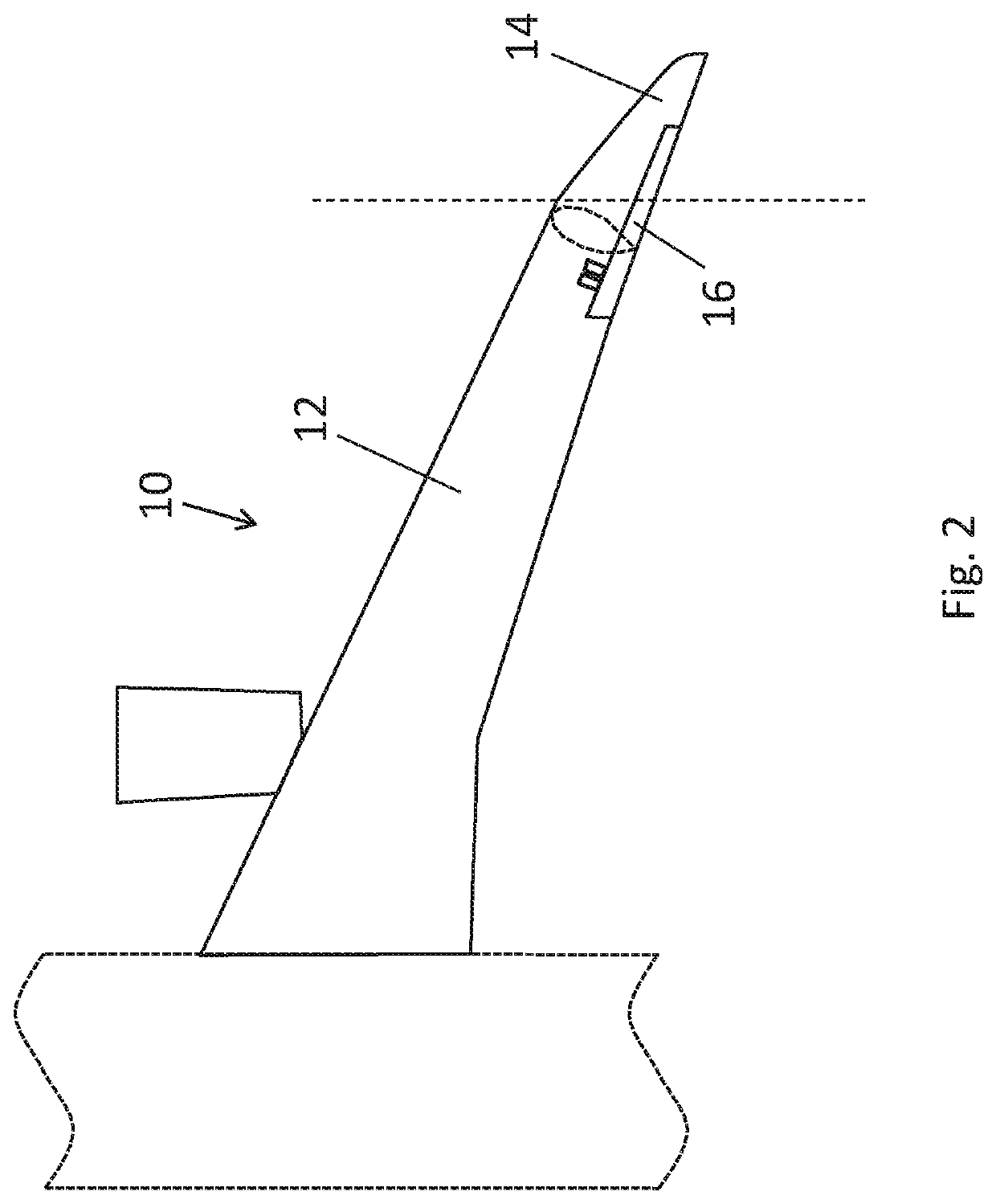
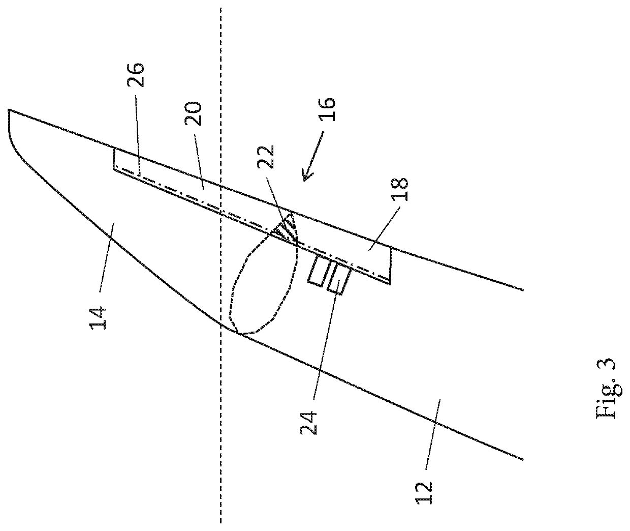
[0041]FIGS. 2 and 3 show the aircraft wing 10 in more detail. The wing 10 comprises a two-part aileron 16 extending across from the fixed wing 12 to the wing tip device 14. The two-part aileron 16 comprises a master aileron 18 and a slave aileron 20. When in the flight configuration, as shown in FIGS. 2 and 3, there is an interface 22 between the master aileron 18 and slave aileron 20. Actuators 24 are arranged to move the master aileron 18 around an aileron hinge axis 26. The interface 22 ...


PUM


Abstract

An aircraft wing having a fixed wing with a wing tip device. The wing tip device is movable between a flight configuration for use during flight, and a ground configuration for use during ground-based operations. The wing has a master flight control surface associated with the fixed wing and a slave flight control surface associated with the wing tip device. An interface between the master flight control surface and the slave flight control surface is arranged to provide a rigid connection between the master flight control surface and slave flight control surface when the wing tip device is in the flight configuration. Moving the master control surface about a control axis causes the slave control surface to be moved about the control axis. The interface is arranged to de-couple the slave and master control surfaces when the wing tip device is moved from the flight configuration into the ground configuration.

Description

RELATED APPLICATION[0001]This application claims priority to United Kingdom (GB) 1617308.0 filed Oct. 12, 2016, the entire contents of which is incorporated by reference.BACKGROUND OF THE INVENTION[0002]The present invention concerns an aircraft wing comprising a flight control surface, for example, an aileron. More particularly, but not exclusively, this invention concerns an aircraft wing comprising an aileron and a wing tip device.[0003]There is a trend towards increasingly large passenger aircraft, for which it is desirable to have correspondingly large wing spans. However, the maximum aircraft span is effectively limited by airport operating rules which govern various clearances required when maneuvering around the airport (such as the span and / or ground clearance required for gate entry and safe taxiway usage). To address this problem, various arrangements comprising moveable wing tip devices, that specifically enable the span to be reduced in a ground configuration, have been...

Claims


Application Information

Patent Timeline
Patent Type & Authority Patents(United States)
IPC IPC(8): B64C3/56B64C23/06
CPCB64C3/56B64C23/072Y02T50/10B64C3/00B64C9/02B64C9/22B64C2009/005B64C3/546B64C9/10
Inventor KELLY, MARK SHAUNALEXANDER, STUART
Owner AIRBUS OPERATIONS LTD
Why Eureka
Try Eureka