
Rotated boundaries of stops and targets

a technology of stops and targets, applied in the field of meteorology, can solve the problems of a large number of applicative problems, and achieve the effects of reducing interruptions, improving accuracy, and reducing performance and accuracy loss

Active Publication Date: 2020-09-01
KLA CORP
View PDF25 Cites 0 Cited by
  • Summary
  • Abstract
  • Description
  • Claims
  • Application Information

AI Technical Summary

Benefits of technology

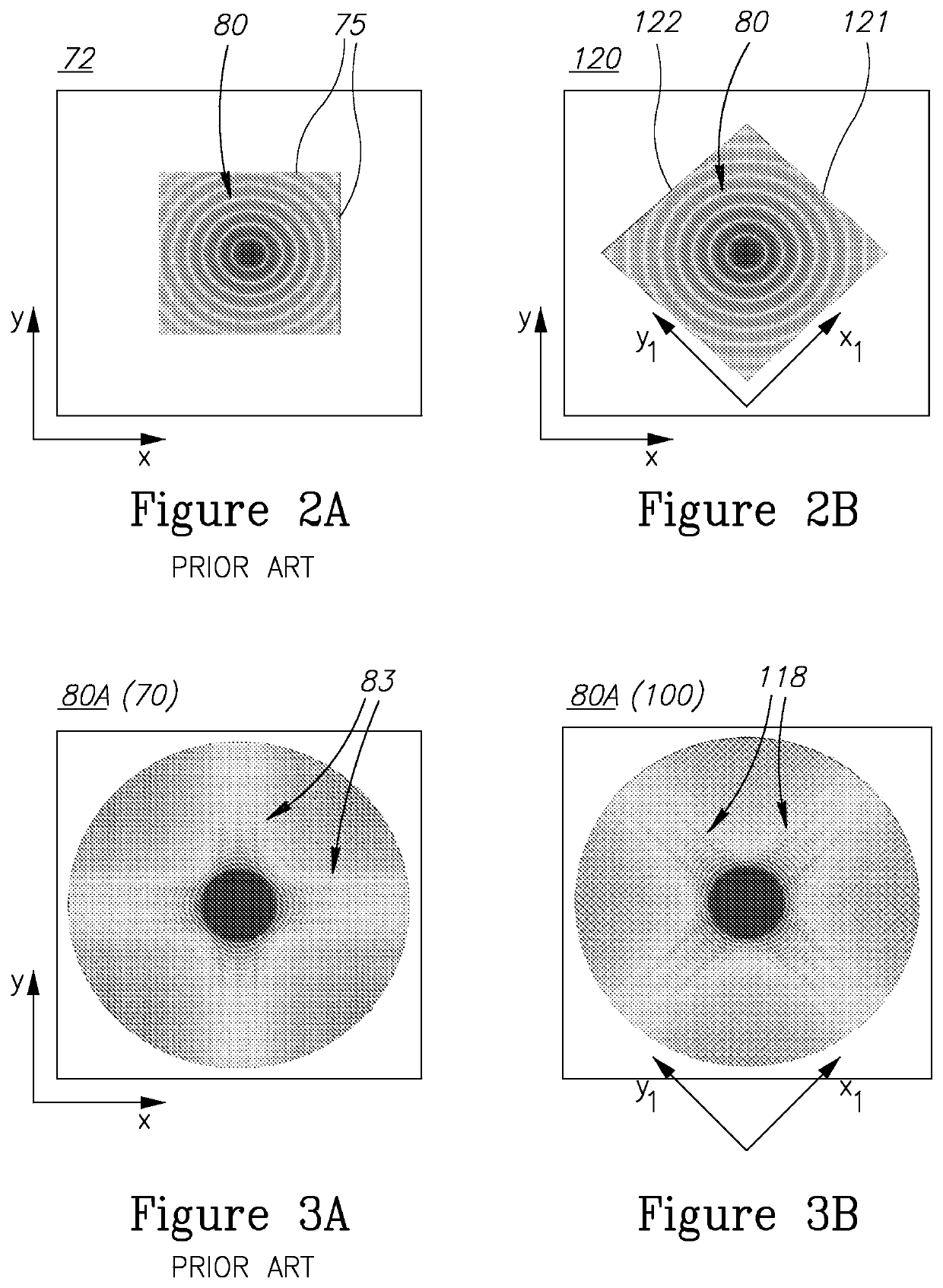
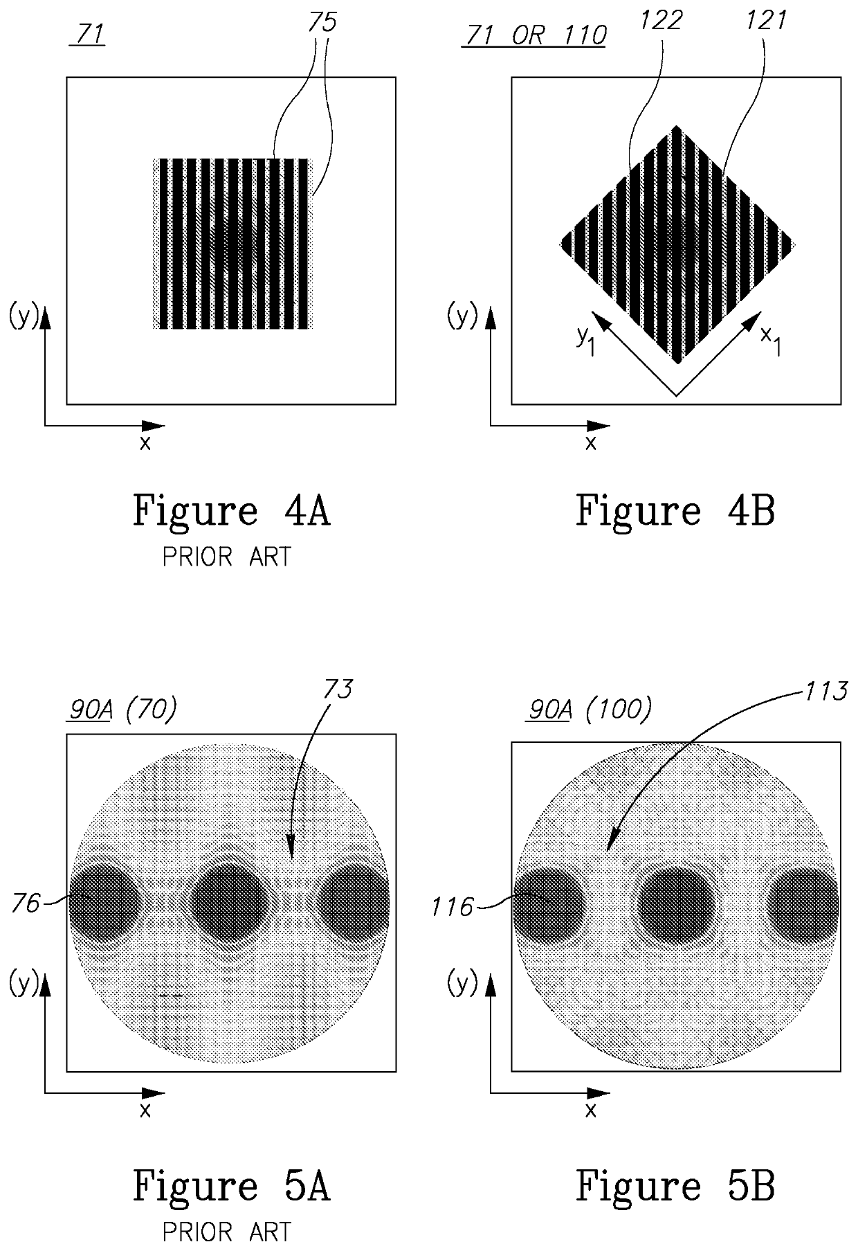
This approach effectively reduces edge diffraction effects, enhancing the accuracy and repeatability of scatterometry measurements by minimizing the interference of edge diffraction with grating diffraction signals and maintaining the symmetry required for precise overlay measurements.

Problems solved by technology

U.S. Patent Publication No. 2011 / 0194092 discloses rotating the actual target grating, which raises a large number of applicative problems.

Method used


Image

  • Rotated boundaries of stops and targets
  • Rotated boundaries of stops and targets
  • Rotated boundaries of stops and targets

Examples


Embodiment Construction

[0039]At the outset, it should be appreciated that like reference characters on different drawing views identify identical, or functionally similar, structural elements of the invention. While the present invention is described with respect to what is presently considered to be the preferred aspects, it is to be understood that the invention as claimed is not limited to the disclosed aspect. Also, it is to be understood that the invention is not limited in its application to the details of construction and the arrangement of the components set forth in the following description or illustrated in the drawings. The invention is applicable to other embodiments or of being practiced or carried out in various ways and is intended to include various modifications and equivalent arrangements within the spirit and scope of the appended claims.

[0040]Furthermore, it is understood that this invention is not limited to the particular methodology, materials and modifications described and as suc...


PUM

PropertyMeasurementUnit
angleaaaaaaaaaa
angleaaaaaaaaaa
angleaaaaaaaaaa

Abstract

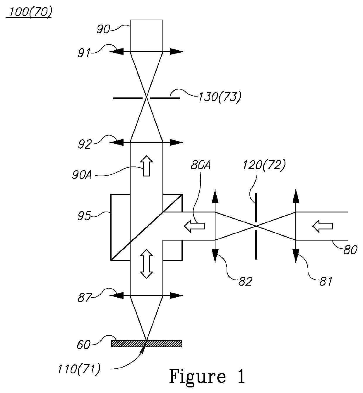
A scatterometry metrology system, configured to measure diffraction signals from at least one target having respective at least one measurement direction, the scatterometry metrology system having at least one field stop having edges which are slanted with respect to the at least one measurement direction.

Description

CROSS-REFERENCE TO RELATED APPLICATIONS[0001]This application is filed under 35 U.S.C. § 111(a) and § 365(c) as a continuation of International Patent Application No. PCT / US2015 / 037167, filed on Jun. 23, 2015, which application claims the benefit of U.S. Provisional Patent Application No. 62 / 016,267, filed on Jun. 24, 2014, which applications are incorporated herein by reference in their entireties.TECHNICAL FIELD[0002]The present invention relates to the field of metrology, and more particularly, to scatterometry metrology optical systems and targets.BACKGROUND OF THE INVENTION[0003]Overlay offset measurement is implemented by an angle resolved scatterometry technology, such as the 4-cell measurement technology. In this arrangement, an illumination radiation is incident on a “grating on grating” target. The target scatters the illumination radiation to form a scattered radiation. A part of the scattered radiation undergoes diffraction by the target. The resulting scattered radiatio...

Claims


Application Information

Patent Timeline
Patent Type & Authority Patents(United States)
IPC IPC(8): G01N21/47G03F7/20G06F30/39G01N21/956
CPCG01N21/4788G06F30/39G03F7/70633G03F7/70683G01N21/4785G01N21/956G03F7/70091G03F7/70625
Inventor GRUNZWEIG, TZAHISVIZHER, ALEXANDER
Owner KLA CORP
Learn More