Method and apparatus for illumination and inspection of an object in a machine vision apparatus

a machine vision and object technology, applied in lighting and heating apparatus, instruments, television systems, etc., can solve the problems of not being able to illuminate an object and hindering so as to facilitate the detection of geometric properties, accurate detection, and hinder the identification of geometric properties

Active Publication Date: 2020-09-15
RENISHAW PLC
View PDF32 Cites 0 Cited by
  • Summary
  • Abstract
  • Description
  • Claims
  • Application Information

AI Technical Summary

Benefits of technology

[0007]In this way, the region of the object may be illuminated sufficiently in order that geometric properties, such as edges of the object, in this region can be accurately detected from the image. In particular, the light panel can be attached to the object to uniformly illuminate regions of the object which cannot be uniformly illuminated from below or by using lights, such as light boxes, mounted remote from the object. For example, it may not be possible to illuminate an object having features that face in significantly different directions using a single light box. The use of multiple light boxes generates gaps that may hinder the identification of the geometric properties, such as the edges of the object. The light panel of the invention when attached to the object may have a shape that substantially corresponds to a shape of the region backlit by the light panel. In this way, substantially uniform, and possibly continuous, backlighting may be achieved across the region of the object to be imaged.
[0008]The light panel may comprise a flexible light panel that can be bent into a desired shape, such as a shape that substantially corresponds to a shape of the region backlit by the light panel. Attaching of the light panel to the object may bend the light panel into the desired shape. The light panel may be electroluminescent sheeting. It has been found that electroluminescent sheeting provides a uniformity of light that aids detection of geometric properties of the region.
[0009]The light panel may be attached to the object using a fixture. The fixture may also attach the object in place in the machine vision apparatus. The fixture may hold the light in the desired shape. The fixture may be arranged such that attachment of the light panel to the object using the fixture results in the light panel being shaped to follow contours of the object, thus providing a suitable shaped light panel to provide uniform illumination over the region to be illuminated.
[0016]The light panel may be attached to the object so as to be located within the object. In this way, the light panel may illuminate a region that would otherwise fall within a shadow cast by the object if the object was backlit by a light located externally to the object.

Problems solved by technology

For example, it may not be possible to illuminate an object having features that face in significantly different directions using a single light box.
The use of multiple light boxes generates gaps that may hinder the identification of the geometric properties, such as the edges of the object.

Method used


Image

  • Method and apparatus for illumination and inspection of an object in a machine vision apparatus
  • Method and apparatus for illumination and inspection of an object in a machine vision apparatus
  • Method and apparatus for illumination and inspection of an object in a machine vision apparatus

Examples


Embodiment Construction

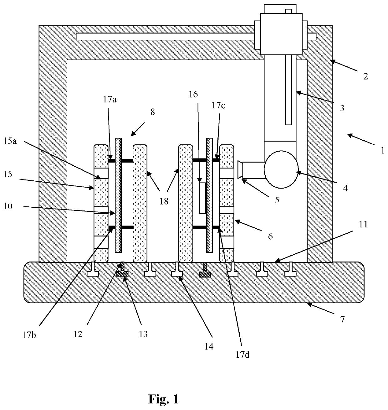
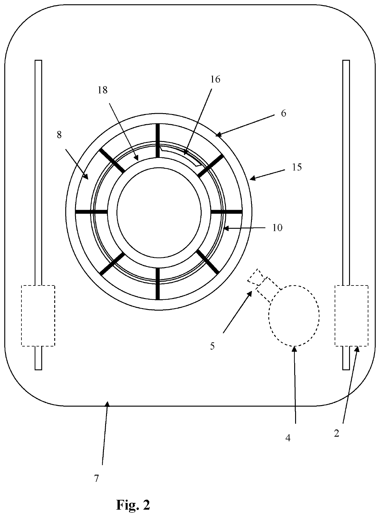
[0047]Referring to the Figures, a machine vision apparatus 1 is a bridge-type (Cartesian) coordinate measuring machine comprises arms 2 for supporting a quill 3, the arms 2 mounted on a base, such as a solid, granite base 7. The base 7 provides a bed 11 on which object 6 can be located. Mounted to the end of the quill 3 is a rotary head 4 carrying a camera 5, in this embodiment a CCD camera. It is also possible to use a CMOS image sensor. The quill 3 can be moved around the object 6 with the rotary head 4 adjusting the position of the camera 5 in order to capture images of the object.

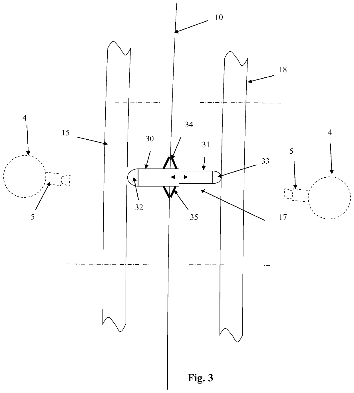
[0048]The object 6 is located on the base 7. A fixture 8 attaches one or more light panels, such as one or more electroluminescent sheets 10, to the object 6 via a plurality of connecting members, four of which are shown as 17a, 17b, 17c and 17d The fixture 8 and the light panel 10 together form a lighting unit.

[0049]Referring to FIG. 3, each connecting member 17a, 17b, 17c, 17d comprises a first member...


PUM

PropertyMeasurementUnit
shapeaaaaaaaaaa
flexibleaaaaaaaaaa
poweraaaaaaaaaa

Abstract

A method of inspecting an object including locating an object on a machine vision apparatus, attaching a light panel to the object to backlight a region of the object, obtaining an image of the region when backlit by the light panel and identifying a geometric property of the object from the image.

Description

FIELD OF INVENTION[0001]This invention concerns a method and apparatus for use in machine vision. The invention has particular, but not exclusive, application to detecting an edge profile of an object through imaging of the object.BACKGROUND[0002]US2011 / 0181715 A1 describes a back-lit vision machine comprising a planar backlight located in a base of a coordinate measuring machine (CMM) for illuminating objects placed on the base. Backlit images are acquired by a CCD camera, these images processed by a computer to measure the location of edges of the object. Backlighting of non-planar parts facilitates the identification of the edges of an object.[0003]For simple objects such apparatus detects edges of the object with the required accuracy. However, it has been found that for complex objects, such as objects comprising a series of overlapping walls or non-planar parts that cannot be uniformly illuminated by the backlight located in the base, edges of the object are not detected with ...

Claims


Application Information

Patent Timeline
Patent Type & Authority Patents(United States)
IPC IPC(8): H04N7/18F21V7/04G01N21/88G01B11/00G01B11/24H04N5/225
CPCH04N5/2256G01B11/2433G01N21/8806H04N23/56
Inventor MCLEAN, CALUM CONNERFEATHERSTONE, TIMOTHY CHARLESDEWAR, RICHARD GEORGE
Owner RENISHAW PLC
Why Eureka
Try Eureka